background image

USER GUIDE

PXIe-1088

This document describes the features of the PXIe-1088 chassis and contains information about
configuring the chassis, installing the modules, and operating the chassis.

Contents

Related Documentation ............................................................................................................2
Getting Started.......................................................................................................................... 2

Unpacking......................................................................................................................... 2
What You Need to Get Started..........................................................................................2
Key Features..................................................................................................................... 3
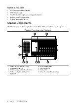
Chassis Components......................................................................................................... 4
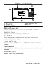
Optional Equipment.......................................................................................................... 5

PXIe-1088 Backplane Overview.............................................................................................. 6

Interoperability with CompactPCI.................................................................................... 6
System Controller Slot...................................................................................................... 6
Hybrid Peripheral Slots.....................................................................................................6
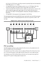
PXI Local Bus...................................................................................................................7
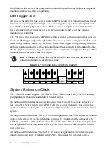
PXI Trigger Bus................................................................................................................ 8
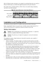
System Reference Clock................................................................................................... 8

Installation and Configuration.................................................................................................. 9

Safety Information............................................................................................................ 9
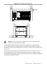
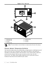
Chassis Cooling Considerations......................................................................................10
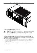
Rack Mounting................................................................................................................13
Connecting the Safety Ground........................................................................................14
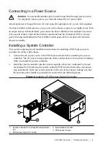
Connecting to a Power Source........................................................................................ 15
Installing a System Controller.........................................................................................15
Installing Peripheral Modules......................................................................................... 16
LED Indicator................................................................................................................. 17
DIP Switches...................................................................................................................18
Inhibit Mode....................................................................................................................19
Fan Mode........................................................................................................................ 19
PXI Express System Configuration with MAX..............................................................20
Using System Configuration and Initialization Files......................................................24

Maintenance............................................................................................................................ 25

Service Interval............................................................................................................... 25
Preparation...................................................................................................................... 25
Cleaning.......................................................................................................................... 25

Worldwide Support and Services............................................................................................ 26

Summary of Contents for PXIe-1088

Page 1: ...System Controller Slot 6 Hybrid Peripheral Slots 6 PXI Local Bus 7 PXI Trigger Bus 8 System Reference Clock 8 Installation and Configuration 9 Safety Information 9 Chassis Cooling Considerations 10 R...

Page 2: ...to the metal work Check to make sure all handles hardware and switches are undamaged Inspect the inner chassis for any possible damage debris or detached components If damage appears to have been caus...

Page 3: ...B s or 2 GB s single direction per PXI Express slot dedicated bandwidth x1 or x4 Gen 2 PCI Express 3 hybrid peripheral slots connect as x4 links to the system slot 5 hybrid peripheral slots connect as...

Page 4: ...y features of the PXIe 1088 chassis front and back panels Figure 1 Front View of the PXIe 1088 PXIe 1088 LOW POWER 2 3 4 1 5 6 7 8 9 1 2 7 6 4 3 5 8 9 1 System Controller Expansion Slot 2 Backplane Co...

Page 5: ...MC Filler Panels EMC filler panel kits are available from National Instruments Slot Blockers PXI Slot Blocker kits are available from National Instruments for improved thermal performance when all slo...

Page 6: ...to peripheral slots as x4 links slots 4 6 and 8 The other system slot link is routed as a x4 link to the PCI Express switch providing x1 PCI Express links to the remaining peripheral slots and the two...

Page 7: ...Local Bus The hybrid peripheral slot connects to only PXI Local Bus 6 left and right Figure 3 PXIe 1088 PCI Express Backplane Diagram x4 x4 x4 x4 x1 x1 x1 x4 x4 x1 x1 x1 x1 x4 Port 15 Port 5 Port 7 P...

Page 8: ...ny trigger line may be routed in either direction it cannot be routed in more than one direction at a time Figure 4 PXI Trigger Bus Connectivity Diagram H H H 7 8 9 H H H H 1 2 3 4 5 6 PXI Trigger Bri...

Page 9: ...us to human life and safety and is capable of inflicting personal injury Chassis Grounding The chassis requires a connection from the premise wire safety ground to the chassis ground The earth safety...

Page 10: ...ection Providing Adequate Clearance The module and power supply intake vents are located on the front left side and bottom of the chassis The module and power supply exhaust vents for the PXIe 1088 ar...

Page 11: ...ck or benchtop use you can monitor the chassis intake temperatures in Measurement Automation Explorer MAX to ensure the temperatures do not exceed the ratings in the Operating Environment section of t...

Page 12: ...Definition The chassis fan control system uses ambient intake air temperatures for controlling fan speeds when in Auto mode These temperatures may be higher than ambient room temperature depending on...

Page 13: ...formance of the chassis can be improved by installing optional slot blockers Refer to the National Instruments website at ni com info and enter the Info Code slotblocker for more information about slo...

Page 14: ...riate earth safety ground If your power outlet does not have an appropriate ground connection you must connect the premise safety ground to the chassis grounding screw located on the rear panel To con...

Page 15: ...uctions for installing a PXI Express system controller in a PXIe 1088 chassis 1 Connect the AC power source to the PXI Express chassis before installing the system controller The AC power cord grounds...

Page 16: ...Refer to your peripheral module user manual for specific instructions and warnings To install a module complete the following steps 1 Connect the AC power source to the PXI Express chassis before inst...

Page 17: ...5 Injector Ejector Rail LED Indicator The following figure shows the front panel Status LED The following table describes the Status LED states Figure 11 Status LED Table 2 Front Panel Status LED Sta...

Page 18: ...off right position Default mode is selected When this switch is in the on left position Manual mode is selected Figure 12 Backplane DIP Switches 1 2 3 4 1 Switch 1 Fan 2 Switch 2 PWR 3 Switch 3 NC 4 S...

Page 19: ...on about the DIP switch Refer to the Front View of the PXIe 1088 Chassis for the location of this switch Fan Mode The PXIe 1088 chassis operates in two main fan modes In Auto mode the speed of the cha...

Page 20: ...automatically identifies your PXI Express system components to generate a pxiesys ini file You can configure your entire PXI system and identify PXI 1 chassis through Measurement Automation Explorer M...

Page 21: ...riant or firmware and platform services version Trigger Configuration in MAX PXI Platform Services provides an interface to route and reserve triggers so dynamic routing through drivers such as DAQmx...

Page 22: ...tic reservation of trigger lines can be implemented by the user in MAX through the Triggers tab PXI modules dynamically configured by programs such as NI DAQmx will not use reserved trigger lines This...

Page 23: ...Figure 14 Trigger Configuration in MAX PXIe 1088 User Guide National Instruments 23...

Page 24: ...se modes You may also select a Manual fan mode In this mode you may manually set the fan speeds to achieve the desired performance Note You may not set the fan speeds or power settings lower than the...

Page 25: ...enance procedures you can perform on the PXIe 1088 chassis Caution Disconnect the power cable prior to servicing your PXIe 1088 chassis Service Interval Clean dust from the chassis exterior and interi...

Page 26: ...at 11500 North Mopac Expressway Austin Texas 78759 3504 NI also has offices located around the world For support in the United States create your service request at ni com support or dial 1 866 ASK M...

Reviews: