background image

Artisan Technology Group 

is your source for quality 

new and certified-used/pre-owned equipment

• 

FAST SHIPPING AND 

DELIVERY

• 

TENS OF THOUSANDS OF 

IN-STOCK ITEMS

•  EQUIPMENT DEMOS
• 

HUNDREDS OF 

MANUFACTURERS 

SUPPORTED

•  LEASING/MONTHLY


RENTALS

•  ITAR CERTIFIED


SECURE ASSET 

SOLUTIONS

SERVICE CENTER REPAIRS

Experienced engineers and technicians on staff 

at our full-service, in-house repair center

WE BUY USED EQUIPMENT

Sell your excess, underutilized, and idle used equipment 

We also offer credit for buy-backs and trade-ins

www.artisantg.com/WeBuyEquipment


REMOTE INSPECTION

Remotely inspect equipment before purchasing with 

our interactive website at


www.instraview.com

LOOKING FOR MORE INFORMATION? 

Visit us on the web at


www.artisantg.com


for more 

information on price quotations, drivers, technical 

specifications, manuals, and documentation

Contact us:


(888) 88-SOURCE  |  sales@artisantg.com  |  www.artisantg.com

SM

View

Instra

Summary of Contents for PXIe-6591R

Page 1: ...service in house repair center WE BUY USED EQUIPMENT Sell your excess underutilized and idle used equipment We also offer credit for buy backs and trade ins www artisantg com WeBuyEquipment REMOTE IN...

Page 2: ...ial Instruments User Manual PXIe 6591R PXIe 6592R PXIe 7902 NI High Speed Serial Instruments User Manual June 2017 374574F 01 Artisan Technology Group Quality Instrumentation Guaranteed 888 88 SOURCE...

Page 3: ...nstruments Corporate Headquarters 11500 North Mopac Expressway Austin Texas 78759 3504 USA Tel 512 683 0100 For further support information refer to the NI Services appendix To comment on National Ins...

Page 4: ...INGEMENT AND ANY WARRANTIES THAT MAY ARISE FROM USAGE OF TRADE OR COURSE OF DEALING NI DOES NOT WARRANT GUARANTEE OR MAKE ANY REPRESENTATIONS REGARDING THE USE OF OR THE RESULTS OF THE USE OF THE PROD...

Page 5: ...ave no agency partnership or joint venture relationship with National Instruments Patents For patents covering National Instruments products technology refer to the appropriate location Help Patents i...

Page 6: ...e by one or more of the following measures Reorient the antenna of the receiver the device suffering interference Relocate the transmitter the device generating interference with respect to the receiv...

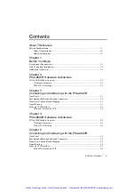
Page 7: ...R Front Panel 3 1 Recommended Mating Cables and Connectors 3 2 Transceiver Lane and Quad Mapping 3 2 Signal Routing 3 3 Socketed CLIP Interface 3 3 PXIe 6591R Socketed CLIP 3 4 Chapter 4 PXIe 6592R Ha...

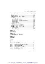
Page 8: ...he IP Core 8 6 Writing a VHDL Wrapper Around the Protocol IP Core 8 8 Constraints and Hierarchy 8 9 Documenting Your IP 8 10 Improving Performance in Larger Designs through Enable Chain Removal 8 10 D...

Page 9: ...26 Power Thermal Protection and Shutdown 8 26 Debugging Clocks Using Frequency Counters 8 26 Debugging Link Connections Using Eye Scan 8 27 Rectangular Eye Scan 8 27 N Point Eye Scan 8 28 Eye Scan Sta...

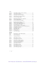
Page 10: ...the Instruction Framework 8 18 Figure 8 7 Create AXI4 Lite Resources vi 8 18 Figure 8 8 Read Module Temperature 8 23 Figure 8 9 Read Module Power 8 24 Figure 8 10 Rectangular Eye Scan 8 25 Figure 8 1...

Page 11: ...Table 6 2 PXIe 7902 Reference Clocks 6 3 Table 7 1 PXIe 7902 Front Panel Connectors 7 2 Table 7 2 Transceiver Lane and Quad Mapping 7 2 Table 7 3 Clock Signal and Quad Mapping 7 3 Table 7 4 PXIe 7902...

Page 12: ...vely Chapters 6 and 7 contain information about the PXIe 7902 hardware architecture and functionality respectively Chapter 8 contains information about how to develop applications for all high speed s...

Page 13: ...Contains installation instructions for your system NI High Speed Serial Instruments Help AvailablefromtheStart menu and at ni com manuals Contains information about how to add FPGA I O to your project...

Page 14: ...A Module With the LabVIEW FPGA Module and LabVIEW you can create VIs that run on National Instruments FPGA targets The Getting Started with the LabVIEW FPGA book provides links to the top resources th...

Page 15: ...x 7 and Virtex 7 devices Kintex 7 FPGAs Data Sheet DC and AC Switching Characteristics DS182 Contains the DC and AC switching characteristic specifications for the Kintex 7 FPGAs Vivado Design Suite R...

Page 16: ...rial devices Table 1 1 Fundamentals Resources Concept Resources High speed serial fundamentals High Speed Serial I O Made Simple A Designers Guide with FPGA Applications available at xilinx com VHDL c...

Page 17: ...tion Installation Instructions Refer to the getting started guide for your device refer to the Related Documentation section of this document for instructions about how to install LabVIEW LabVIEW FPGA...

Page 18: ...ers or you can develop your own protocol IP If you develop your own protocol IP the IP must be developed for a Xilinx Kintex 7 GTX transceiver Note The PXIe 6591R hardware does not require calibration...

Page 19: ...ectors Port 0 and Port 1 for high speed serial I O One SMA CLK IN OUT connector for external clock routing One VHDCI Digital Data Control for 20 general purpose input output lines FPGA Kintex 7 410T F...

Page 20: ...1R clocking architecture includes the following MGT Reference Clocks MGT_RefClk0 MGT_RefClk1 MGT_RefClk0 and MGT_RefClk1 are separate clocks but are derived though simple integer division of a common...

Page 21: ...ates the clocking circuitry on the PXIe 6591R Figure 2 2 PXIe 6591R Clocking Diagram CLK IN OUT PORT 0 PORT 1 PXIe_Clk100 PXIe_DStarA MGT_RefClk1 MGT_RefClk0 FPGA Clock Synthesis and Routing Artisan T...

Page 22: ...B9 C1 C2 C3 C4 C5 C6 C7 C8 C9 D1 D2 D3 D4 D5 D6 D7 D8 D9 RESERVED GND DIO 0 RESERVED DIO 2 GND DIO 4 GND DIO 6 GND DIO 8 GND DIO 10 GND DIO 12 RESERVED DIO 14 GND DIO 16 GND DIO 18 GND GND RESERVED G...

Page 23: ...ansceiver and RefClk selection when using the Xilinx tools to generate protocol IP Table 3 1 PXIe 6591R Front Panel Connectors Connector Type Description CLK IN OUT SMA Reference Clock input and expor...

Page 24: ...al differential signals are routed directly from the Kintex 7 FPGA pins to the PORT 0 and PORT 1 connector pins using a 100 nF AC coupling capacitor as shown in the following figure Figure 3 2 PXIe 65...

Page 25: ...lk0_p In pad N A Differential input clock that you must connect to an IBUFDS_GTE2 input buffer primitive when this input clock is used in your design MGT_RefClk0_n In pad N A MGT_RefClk1_p In pad N A...

Page 26: ...signals into any CLIP that depends on the MGT_RefClkx signals On the rising edge of MGT_ RefClks_Valid you may need to reset or relock state machines and or internal PLLs sensitive to MGT_RefClkx sig...

Page 27: ...aults and power faults This signal is conditioned with the pulse stretcher to guarantee a minimum assertion time of 100 ms to comply with PXI guidelines and to facilitate visual perception You can dri...

Page 28: ...ly with PXI guidelines and to facilitate visual perception You can drive this signal asynchronously if you provide a 50 ns minimum assertion time You can also drive this signal synchronously for a min...

Page 29: ...n occurs unconditionally The required clocking signals are not valid until after this signal asserts high sFrontEndConfiguration Prepare In SocketClk40 Reserved for future use NI recommends assigning...

Page 30: ...t this signal Do not use CLIP inputs from the LabVIEW FPGA VI in the CLIP until aResetSl is deasserted Port 0 1 _RX_p 3 0 In pad N A Dedicated MGT receive signals for Port 0 1 Port 0 1 _RX_n 3 0 In pa...

Page 31: ...ector while it is inserted into the module Port 0 1 _GPIO_Out Out Async This signal is unused Port 0 1 _GPIO_ OutEnable_n Out Async You must tie this signal to 1 to disable output and allow the B2 pin...

Page 32: ...signals along with DDC_GPIO_In 19 0 and DDC_GPIO_OutEnable_ n 19 0 allow control and monitoring of the DIO 19 0 connections on the DDC_ VHDCI connector DDC_GPIO_OutEnable_ n 19 0 Out Async These signa...

Page 33: ...ers or you can develop your own protocol IP If you develop your own protocol IP the IP must be developed for a Xilinx Kintex 7 GTX transceiver Note The PXIe 6592R hardware does not require calibration...

Page 34: ...rs Port 0 Port 1 Port 2 and Port 3 for high speed serial Four SMB connectors PFI 0 CLK IN OUT PFI 1 CLK OUT PFI 2 CLK OUT and PFI 3 CLK OUT for external triggering and clock input output FPGA Kintex 7...

Page 35: ...owing MGT Reference Clocks MGT_RefClk0 MGT_RefClk1 MGT_RefClk2 MGT_RefClk0 and MGT_RefClk1 are separate clocks but are derived though simple integer division of a common higher frequency PLL clock MGT...

Page 36: ...xport a clock from the module all of the PFI connectors must be the same frequency The following figure illustrates the clocking circuitry on the PXIe 6592R Figure 4 2 PXIe 6592R Clocking Diagram Tabl...

Page 37: ...or the PXIe 6592R front panel connectors Figure 5 1 PXIe 6592R Front Panel Connectors and Pinout x4 1 per Port VeeR RD RD VeeR VccR VccT TD VeeT TD VeeT VeeR RS1 Rx_LOS RSO MOD_ABS SCL Tx_Disable SDA...

Page 38: ...about transceiver and RefClk selection when using the Xilinx tools to generate protocol IP Table 5 1 PXIe 6592R Front Panel Connectors Connector Type Description PFI 0 CLK IN OUT SMB Reference Clock...

Page 39: ...gure Figure 5 2 PXIe 6592R Signal Routing Socketed CLIP Interface Socketed CLIP allows you to insert HDL IP into an FPGA target enabling VHDL code to communicate directly with an FPGA VI Socketed CLIP...

Page 40: ..._n In pad N A MGT_RefClk1_p In pad N A MGT_RefClk1_n In pad N A MGT_RefClk2_p In pad N A Fixed 156 25 MHz Reference Clock for the transceivers that you must connect to an IBUFDS_GTE2 input buffer prim...

Page 41: ...signals into any CLIP that depends on the MGT_RefClkx signals On the rising edge of MGT_ RefClks_Valid youmayneed to reset or relock state machines and or internal PLLs sensitive to MGT_RefClkx signa...

Page 42: ...aults and power faults This signal is conditioned with the pulse stretcher to guarantee a minimum assertion time of 100 ms to comply with PXI guidelines and to facilitate visual perception You can dri...

Page 43: ...ly with PXI guidelines and to facilitate visual perception You can drive this signal asynchronously if you provide a 50 ns minimum assertion time You can also drive this signal synchronously for a min...

Page 44: ...n occurs unconditionally The required clocking signals are not valid until after this signal asserts high sFrontEnd ConfigurationPrepare In SocketClk40 Reserved for future use NI recommends assigning...

Page 45: ...l Do not use CLIP inputs from the LabVIEW FPGA VI in the CLIP until aResetSl is deasserted Port 0 3 _RX_p In pad N A Dedicated MGT receive signals for Port 0 3 Port 0 3 _RX_n In pad N A Port 0 3 _TX_p...

Page 46: ...Gbps or less drive this signal low Port 0 3 _Rx_LOS In Async This signal is driven by the Port 0 3 SFP module to indicate that the SFP module cannot detect an RX signal Port 0 3 _Tx_Disable Out Async...

Page 47: ...nal serial data signal for the two wire communication interface on the Port 0 3 connector Valid values are 0 and Z open drain This signal is also called MODDEF2 This signal has a 10 k pull up to 3 3V...

Page 48: ...PIO_In In Async Acquires GPIO input from the PFI 0 3 connectors PFI 0 3 _GPIO_Out Out Async Drives the GPIO output data to the PFI 0 3 connectors PFI 0 3 _GPIO_ OutEnable_n Out Async Enables or disabl...

Page 49: ...ers or you can develop your own protocol IP If you develop your own protocol IP the IP must be developed for a Xilinx Virtex 7 GTX transceiver Note The PXIe 7902 hardware does not require calibration...

Page 50: ...Connectors Six mini SAS x4 connectors Port 0 Port 1 Port 2 Port 3 Port 4 and Port 5 for high speed serial One SMB connector CLK IN for clock input FPGA Xilinx Virtex 7 485T FFG1158 package FPGA speed...

Page 51: ...e following MGT Reference Clocks MGT_RefClk0 MGT_RefClk1 MGT_RefClk2 MGT_RefClk0 MGT_RefClk1 and MGT_RefClk2 are separate clocks but are derived though simple integer division of a common higher frequ...

Page 52: ...ry on the PXIe 7902 Figure 6 2 PXIe 7902 Clocking Diagram CLK IN PORT 4 PORT 5 PORT 0 PORT 1 PORT 2 PORT 3 Clock Synthesis and Routing PXIe_Clk100 PXIe_DStarA MGT_RefClk0 MGT_RefClk1 MGT_RefClk2 FPGA...

Page 53: ...XIe 7902 Front Panel Connectors and Pinout PXIe 7902 CLK IN PORT 2 PORT 4 PORT 5 PORT 3 PORT 0 PORT 1 RESERVED RESERVED GND Rx 1 Rx 1 GND Rx 3 Rx 3 GND SCL SDA GND Tx 1 Tx 1 GND Tx 3 Tx 3 GND Optical...

Page 54: ...for information about transceiver and RefClk selection when using the Xilinx tools to generate protocol IP Table 7 1 PXIe 7902 Front Panel Connectors Connector Type Description CLK IN SMB Reference C...

Page 55: ...replicated for every lane across every port Figure 7 2 PXIe 7902 Signal Routing Socketed CLIP Interface Socketed CLIP allows you to insert HDL IP into an FPGA target enabling VHDL code to communicate...

Page 56: ...tion MGT_RefClk2_p In pad N A Differential input clock that you must connect to an IBUFDS_ GTE2 input buffer primitive when this input clock is used in your design MGT_RefClk2_n In pad N A MGT_RefClk3...

Page 57: ...al Some MGT signals have inverted polarity external to the FPGA use this signal to determine which channels if any are inverted GtxTxPolarity_in In pad 24 bit signal that indicates the polarity of the...

Page 58: ...SDA In Out Async Bidirectional serial data signal for the two wire communication interface on the Port 0 3 connector Valid values are 0 and Z open drain This signal is also called MODDEF2 This signal...

Page 59: ...nals into any CLIP that depends on the MGT_RefClkx signals On the rising edge of MGT_ RefClks_Valid youmayneed to reset or relock state machines and or internal PLLs sensitive to MGT_RefClkx signals D...

Page 60: ...rontEnd ConfigurationPrepare In SocketClk40 Reserved for future use NI recommends assigning this signal to sFront EndConfigurationReady sFrontEnd ConfigurationReady Out SocketClk40 Reserved for future...

Page 61: ...r disables the optical power supply on Port 0 5 Assert this signal to enable the optical supply for its corresponding port aOptical_Power Good In SocketClk40 Indicates that the optical power supply fo...

Page 62: ...y with an FPGA VI Allows the CLIP to communicate directly with circuitry external to the FPGA Allows your IP to communicate directly with both the FPGA VI and the external FPGA module connector interf...

Page 63: ...versions of the tool on your machine by selecting Start Control Panel Programs and Features Note If Vivado is installed by LabVIEW FPGA it does not appear in Programs and Features 2 Open the Xilinx V...

Page 64: ...Ie 6591R PXIe 6592R and PXIe 7902R provide out of the box support that demonstrates how to use hardware design files as an entry point when exporting to Vivado Complete the following steps to export a...

Page 65: ...ote The hierarchy source is encrypted except for the design files prefixed with UserRTL_ and added to the FPGA target as a socketed CLIP 6 Navigate to the UserRTL_ files in the hierarchy 7 Use the une...

Page 66: ...xample of how to use the LabVIEW FPGA AXI4 Lite adapters to connect to DRP within the CLIP Modifying Third Party IP Core Logic If you modify a third party IP core for your high speed serial protocol c...

Page 67: ...from the IP core 1 Open the example project for your IP core in Vivado 2 Set the appropriate top level source file for which you plan to generate a netlist 3 Run synthesis 4 Open the Synthesized Desi...

Page 68: ...ule_i enter the following command write_edif cell clock_module_i aurora_64b66b_clock_module edf Note You may have to specify a longer path name depending on the location of the cell in your project Fo...

Page 69: ...LabVIEW FPGA diagram Document the frequency of clocks coming from CLIP Consider supporting enable chain removal Refer to the Improving Performance in Larger Designs through Enable Chain Removal sectio...

Page 70: ...of the component within the overall VHDL hierarchy In such cases consider prefacing the constraints with the following macros Prefacing allows the constraints to be applied regardless of the componen...

Page 71: ...an affect which ports are active with your IP and the behavior of cables upon insetion and removal Use the DebugClks signal to determine the health of the internal clocks being sent to the IP Define w...

Page 72: ...og box 3 Select New target or device and select your device 4 Add the protocol IP through your CLIP Right click the device name and select Properties Component Level IP Note If you are using example C...

Page 73: ...locking and IO Configuration tabs are already configured If you create a new project default values are configured but you must review the settings and ensure that they are correct If you insert a CLI...

Page 74: ...tional placement constraints to your project based on the lanes you select so ensure that you select all lanes used in your project 15 Under GPIO Configuration use the Voltage Family selector box to s...

Page 75: ...abled as output clocks PFI 0 CLK IN OUT PFI 1 CLK OUT PFI 2 CLK OUT and PFI 3 CLK OUT must share the same frequency The output of any enabled PFIx line is 10 MHz when Enable CPRI Output Clock Configur...

Page 76: ...VHDL IP inside CLIP or IPIN To use existing IP in your project refer to the Importing External IP Into LabVIEW FPGA white paper at ni com CLIP does not support custom user libraries in the VHDL If yo...

Page 77: ...ame palette The following sections provide an overview of the instrument design libraries For more information about the instrument design libraries refer to the NI High Speed Serial Instruments Help...

Page 78: ...lting responses The instructions are sent to the FPGA using a uniquely named DMA FIFO and the responses are received using a uniquely named indicator Some instrument design libraries use the Instructi...

Page 79: ...he LabVIEW context help for the Data Trigger VIs This library supports various data types and samples per cycle Using niInstr Basic Elements The Basic Elements Instrument Design Library contains VIs t...

Page 80: ...ore information about how to use high speed serial VIs Refer to the Aurora sample projects for information about how to use the AXI4 Stream wrappers in an application Connecting Signals to Enable Eye...

Page 81: ...Create AXI4 Lite Resources vi which is used by each Aurora sample project This VI creates an AXI4 Lite CLIP Adapter object using the specified CLIP Resources Add Address Map Element vi registers the...

Page 82: ...rate Xilinx or other third party licensed cores LabVIEW and System Integration The following sections contain information about how to integrate your high speed serial system in the LabVIEW applicatio...

Page 83: ...the FIFO larger consumes block RAM resources on the FPGA and increases the timing pressure on the FIFO NI recommends making the FIFO as large as you can successfully compile with in order to sustain...

Page 84: ...Peer to Peer Streaming Throughput Maximum throughput is dependent on the streaming modules chassis and if the configuration warrants it the controller Generally the lowest of these rates is the maxim...

Page 85: ...lines Reserving Trigger Lines in MAX If you download and run the FPGA VI interactively configure the PXI triggers in MAX MAX maintains the trigger reservation for the device even after you cycle powe...

Page 86: ...nction to the error in input of the Invoke Method function 5 Click the Invoke Method function and select Unreserve PXI Trigger from the shortcut menu 6 Right click the Trigger input and select Create...

Page 87: ...display an error screen In order to avoid this issue monitor temperature and power consumption closely when developing custom FPGA images If a power and thermal shutdown occurs power cycle the system...

Page 88: ...ular Eye Scan to obtain a traditional eye that sweeps the unit interval and nominal voltage Use N Point Eye Scan to measure the Bit Error Ratio at arbitrary unit interval and nominal voltage offsets F...

Page 89: ...igh speed serial sample projects the GTX2_CHANNEL UID is nested under the top level UID If you use a different child context UID for GTX2_CHANNEL modify the niHighSpeedSerial Eye Scan Single Point v1...

Page 90: ...on target input terminal of niHighSpeedSerialEyeScan v1 Host lvclass Open Session vi and the context from niInstr Subsystem Map v1 Host lvclass Subsystem Lookup vi to the parent context terminal of ni...

Page 91: ...Measure Poly vi with a relatively small timeout value in a loop This allows you to receive updates to the progress of Eye Scan while measurements are still being taken and provides updates without usi...

Page 92: ...o your LabVIEW project refer to Knowledge Base article 6R6EOLM3 For information about troubleshooting problems adding your high speed serial instrument to your Real Time system refer to Knowledge Base...

Page 93: ...82 Contains the DC and AC switching characteristic specifications for the Kintex 7 FPGAs Vivado Design Suite Release Notes Installation and Licensing UG973 Provides an overview of the new release of t...

Page 94: ...ility requirements and provides warranty sparing and calibration services to help you maintain accuracy and minimize downtime over the life of your system Visit ni com services for more information Wa...

Page 95: ...tted online receives an answer Software Support Service Membership The Standard Service Program SSP is a renewable one year subscription included with almost every NI software product including NI Dev...

Page 96: ...used to read and write DRAM DRAM Dynamic random access memory F FPGA Field programmble gate array G GPIO General purpose input output H HSS High speed serial I IC Integrated circuit IP Intellectual pr...

Page 97: ...nsceiver P PFI Programmable function interface POSC Power on self configuration S SCTL Single cycle timed loop SFP Enhanced small form factor pluggable Artisan Technology Group Quality Instrumentation...

Page 98: ...service in house repair center WE BUY USED EQUIPMENT Sell your excess underutilized and idle used equipment We also offer credit for buy backs and trade ins www artisantg com WeBuyEquipment REMOTE IN...

Reviews: