background image

1 Installation and Troubleshooting
Guide

Navman Wireless

Installation and
Troubleshooting
Guide

October 22, 2014

Version Number and status: 1.0
Document Date: October 22, 2014
Security Classification: Internal Use Only
Document Owner: Gene Guller

Summary of Contents for Qube 300

Page 1: ...Troubleshooting Guide Navman Wireless Installation and Troubleshooting Guide October 22 2014 Version Number and status 1 0 Document Date October 22 2014 Security Classification Internal Use Only Document Owner Gene Guller ...

Page 2: ...Power wire 18 1 7 2 Vehicle s Ignition wire 18 1 7 3 Poke Wrap Solder less Connections 20 1 8 Chassis Ground Connection 22 1 9 Mobile Data Terminal M Nav 800 23 1 10 ConEx Sensor Monitoring Auxiliary Devices 25 1 10 1 Digital Inputs DI 1 to DI 4 25 1 10 2 Digital Outputs DO 1 DO 2 26 1 11 Qube Power Up Procedure 27 1 12 Tamper Evident Seal 28 1 13 Troubleshooting 29 1 13 1 Qube 300 is not powering...

Page 3: ... piece of hardware 33 1 13 9 Power M Nav will not power M Nav loses power unexpectedly M Nav turns on and off while in use 33 1 13 10 Messaging M Nav can t send or receive messages 33 1 13 11 Driver ID Driver Logon function not working 33 1 14 Dimensions and Specifications 34 1 15 Contacts 37 ...

Page 4: ...LY BE EXCLUDED ARE EXPRESSLY EXCLUDED INCLUDING WITHOUT PREJUDICE TO THE GENERALITY OF THE FOREGOING THE IMPLIED WARRANTIES OR MERCHANTABILITY AND FITNESS FOR A PARTICULAR PURPOSE TO THE MAXIMUM EXTENT PERMITTED BY LAW NAVMAN WIRELESS DISCLAIMS ALL LIABILITY ARISING OUT OF OR IN CONNECTION WITH THE PRODUCT INCLUDING ANY USE OF THIS PRODUCT IN A WAY THAT MAY CAUSE ACCIDENTS DAMAGE OR VIOLATE THE LA...

Page 5: ...d monitored It is a combined GPS Global Positioning System and communications product that contains l a GPS Receiver to provide accurate location data l a Cellular Modem that enables data to be transferred between the vehicle and the server l an on board microprocessor to allow data processing and storage and external com munication 1 1 2 Audience This Installation Manual is written for a professi...

Page 6: ...r means to connect wires Failing to ensure proper con nections may result in warranty being voided and damage to the Qube and or the vehicle Ensure that all wiring is protected from heat sources and sharp metal edges and is routed in such manner that it will not get damaged or pinched when vehicle components and trim are reinstalled Run new wiring along factory harnesses and secure with quality ca...

Page 7: ...Supplies 1 3 1 Basic Tools l Wire Strippers l Connector Crimping Tool l Panel Removal Tool l Digital Multimeter DMM l T 10S Security Torx Screwdriver 1 3 2 Basic Supplies l Wire Ring Terminals l Cable Zip Ties l Electrical Tape l Spare Fuses Mini 3A l Self Tapping Screws ...

Page 8: ... provides an install hardware kit for all new Qube systems 1 4 1 Qube 300 Box Contents NOTE You can use a combi antenna OR a separate GPS Antenna and a separate Cellular Antenna Contact your Navman Wireless dealer for advice on the best choices for your type of install ation and for ordering information if necessary ...

Page 9: ... Wireless digital temperature probes and Installation Manual l Satellite Modem cable NOTE The 3 Wire Power cable the GPS Antenna and the Cellular Antenna are the minimal requirement for tracking only 1 4 2 Qube Installation Supplies Kit US only To allow for quicker and easier installations Navman Wireless designed an all in one antenna system that includes both GPS and cellular components built in...

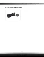
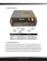
Page 10: ...1 Installation and Troubleshooting Guide 10 1 4 3 GPS Cellular Combination Antenna ...

Page 11: ...security cover onto the front of the Qube over the cables then push it down in place The upper part of the security cover should sit snugly against the lower part with no gap between them The three screw holes should align with the screw pillars of the security cover Insert the two short secur ity screws into the screw holes on the outer edges of the Qube 300 and the long security screw into the c...

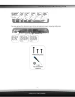
Page 12: ...1 Installation and Troubleshooting Guide 12 ...

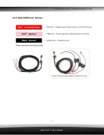
Page 13: ...1 Installation and Troubleshooting Guide 13 1 4 6 Qube 300 Power Harness ...

Page 14: ... under top dash cover and positioned horizontally Make sure the correct side of antenna is facing up towards the sky NOTES l Do not mount the GPS antenna under any metal structure or near the vehicle s radio Avoid mounting the antenna under dashboard in areas where metal clipboards laptops loose change etc may be placed on top of the dash These items may inadvertently block the GPS signal to the a...

Page 15: ...lain site or visible to the driver l the physical orientation of the Qube 300 is not important since the accelerometer is self calibrating The following locations within the vehicle may be suitable l inside or underneath the dash l in the boot trunk area CAUTION Ensure that any mounting holes that need to be cut in the vehicle will not weaken the vehicle structure or compromise the safety of the v...

Page 16: ...Blow 4 Pink Ignition Detect Positive input from vehicle when the key is in the IGNITION pos ition not the Accessory position This signal must remain ON DURING engine cranking star tup This connection must be fused 3 Amp Slow Blow 1 Connect the 3 Wire Power cable to the 4 Way PWR connector at position 2 2 Check that the SIM Card is inserted at position 5 3 Screw the Cellular Antenna connector to th...

Page 17: ...position 7 5 Secure both antenna connectors using an open ended 8mm spanner Complete the installation by securing all wires with zip ties away from any moving parts or sharp metal edges Reconnect any of the vehicle s connectors that were unplugged during disassembly and replace all interior trim panels ...

Page 18: ... accessible or amperage restriction exists or the vehicle has an electronic starting system Qube s constant power and ignition con nections can be made at the interior fusebox 4 Use a multimeter and the chart on next page to identify Constant and Ignition wires 1 7 1 Vehicle s Constant Power wire The correct source wire will have battery voltage present at all times even when the ignition key is i...

Page 19: ...been identified it is strongly recommended that one of the battery post cables is disconnected prior to making wire connections l If the vehicle has a master battery disconnect switch Qube s power must be sourced at the battery or the hot side of the master battery disconnect switch ...

Page 20: ...nch of insulation from the source wire in the vehicle Next strip about 1 of insulation from your fuse holder s wire 2 Poke Use a sharp tool to divide exposed strands of the source wire down the middle cre ating a gap 3 Insert Insert fuse holder s stripped wire through the gap in the source wire Squeeze the gap shut 4 Twist Tightly twist exposed lead of the fuse holder around the bare section of ve...

Page 21: ...1 Installation and Troubleshooting Guide 21 NOTE To ensure long lasting secure connections do not use butt connectors t taps or fuse taps in your installation ...

Page 22: ...is Ground Connection l Connect the Qube s Ground wire black to vehicle s chassis l For a solid connection use a ring tongue terminal connector star washer and a self tap ping screw l Do not ground under existing bolts that hold brackets or panels in place ...

Page 23: ...minal M Nav 800 Route the M Nav800 Power Data cable from the Qube to the top of dashboard where M Nav800 will be mounted Use the supplied suction cup mount or the optional dash mount bracket to secure the device in place Plug into the Data Port RJ45 on the Qube 300 ...

Page 24: ...1 Installation and Troubleshooting Guide 24 ...

Page 25: ...tional I O cables as follows Connection to the serial and digital analogue I O is made through the RJ45 Connector MDT at position 1 8 Way Expansion Pin Connector I O B at position 3 10 Way Expansion Pin Con nector I O A at position 4 1 10 1 Digital Inputs DI 1 to DI 4 The Digital Inputs can be configured to detect high voltages Active High OR low voltages Act ive Low Active High Input Configuratio...

Page 26: ...becomes low The voltage thresholds that trigger the change in input state are as follows 1 10 2 Digital Outputs DO 1 DO 2 The Digital Outputs will pull to Ground and sink a maximum current of 250 mA when activated The outputs have over current trip protection and if tripped the output must be changed to OFF or have a power cycle to reset the current trip ...

Page 27: ...w of the sky 2 Attach both antenna cables to the Qube 3 Plug in power cable 4 Turn ignition key ON to wake Qube from hibernation 5 Wait for all LED lights on the Qube to stay on not flashing NOTE If any LED s are not solid On within 10 minutes perform a Cold Reset 6 Connect optional cables ConEx M Nav MDT etc 7 Log in to Navman Wireless Install Technician Service Portal to perform Live Test US onl...

Page 28: ...e Seal or inspector s lacquer to all Poke and Wrap connections fuse holders and the ground screw Once applied it sticks to the surface and dries hard over 24 hours Once hard it will crack on removal making the tampering obvious Attach the clear tamper proof Security Cover with supplied T 10S security screws ...

Page 29: ...al operation 4 Perform Qube power up test at the vehicle s battery see picture below Check OnlineAVL2 if the Qube resumed normal operation 5 Make sure all unused wires from all Qube s harnesses are individually isolated taped cut off tinned ends off all unused wires Perform Cold Reset Check OnlineAVL2 if the Qube resumed normal operation 6 If a spare working Qube is available plug it in to verify ...

Page 30: ...s for the Qube to establish a network connection Cycle ignition key ON OFF ON Check OnlineAVL2 if the Qube resumed normal operation 6 Check cell antenna connection to the Qube tighten if necessary Check antenna cable for cuts nicks if damaged replace antenna and cable Perform a Cold Reset after replace ment Check OnlineAVL2 if the Qube resumed normal operation 7 Make sure all unused wires from all...

Page 31: ... Remove any obstructions clipboards laptops bean bag mounts portable navigation sys tems Sirius XM sat radios loose coins etc from top of dashboard windshield where the covert antenna may be located Ignition cycle and check OnlineAVL2 if the Qube resumed normal operation 5 Access the antenna location and verify that the correct side of the antenna is facing up sky the flat side with adhesive tape ...

Page 32: ... The installer may have connected the ignition wire from the Qube s power har ness to a constant 12v source in vehicle Use mutimeter to verify wiring connections to Qube s constant 12V ignition and ground wires 1 13 6 Qube is reporting to AVL2 but has multiple Ignition On Ignition Off events This condition is most likely caused by either poor loose connection of the Qube s ignition wire improper s...

Page 33: ...e in Malfunctioning Vehicle test and note any change in M Nav behavior If problem persists proceed to next step 6 Replace the Qube in Malfunctioning Vehicle with a spare or a known working Qube test M Nav and note any change 7 Once failed hardware component is isolated contact Navman Support for return re placement 1 13 9 Power M Nav will not power M Nav loses power unexpectedly M Nav turns on and...

Page 34: ...mA 35 mA l Awake average transmit event once every one minute 120 mA 60 mA l Peak transmit current 250 mA 130 mA l Battery charging additional 150 mA 80 mA Power Supply l Nominal operating voltage 12 or 24 V vehicle supplies l Minimum operating voltage 8 V DC l Maximum operating voltage 30 V DC Digital Output l Maximum sink current 250 mA over cur rent protection shut off Temperature Monitoring l ...

Page 35: ...w mode l Absolute Maximum Voltage 33 V Independent of supply Analogue Input l Voltage Range 0 33 V DC l ADC Resolution 12 bit l Absolute Maximum Voltage 40 V DC Serial Interface l RS232 x 3 Environmental l Storage Temperature 40 to 85 C 40 to 185 F l Operational Temperature 20 to 70 C 4 to 158 F l IP Rating IP4X l Humidity SAE J1455 l Vibration SAE J1455 l Shock 20G 10mS Ignition Input l Absolute ...

Page 36: ...t OR Digital Output OR Ana logue Input 2 5 Light Blue Black RXD 2 RS232 Serial Port 2 Data Input 6 Light Blue TXD 2 RS232 Serial Port 2 Data Output 7 Orange 1 W Temperature Probe Power Supply 8 Orange White 1 WD Temperature Probe Data 10 Way Expansion Pin Connector Pin 8 Wire Cable Colour Function Description 1 Black GND Ground 2 Brown TXD 3 RS232 Serial Port 3 Data Output 3 Brown White RXD 3 RS23...

Page 37: ...LEET 0800 477 353 Email info nz navmanwireless com Website www navmanwireless co nz Navman Wireless Scandinavia Kometvej 10 DK 6230 Rødekro Danmark Tel Danmark 45 70 269 732 Tel Sweden 46 8 559 21 916 Tel Finland 35 89 2316 3595 Navman Wireless Italy Via Rudone 23rd Rovato 25 038 Italia Tel 39 030 615 6468 Website www navmanwirelessitaly it Navman Wireless Taiwan 3 25Fl No 508 Sec 5 Zhongxiao E Rd...

Reviews: