background image

Kit Instructions

Tri-Light/Lane Light with Camera Assembly and
Lane Light Label

7360-K068
Issue C

Summary of Contents for 7360-K068

Page 1: ...Kit Instructions Tri Light Lane Light with Camera Assembly and Lane Light Label 7360 K068 Issue C...

Page 2: ...documentation is permitted under the terms and conditions of an agreement you have with NCR NCR s copyright notice must be included It is the policy of NCR Corporation NCR to improve products as new...

Page 3: ...iii Revision Record Issue Date Remarks A Nov 2019 First Issue B Jun 2020 Updated Username from Admin to admin C Dec 2021 Added Routing Tri Light Lane Light Cable on page 22...

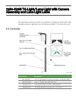
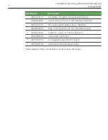
Page 4: ...ght with Camera Assembly and Lane Light Label to an NCR FastLane SelfServ Checkout 7360 unit Kit Contents Part Number Description 497 0526847 Kit Tri light with IP Camera and Label Preferred Offer 497...

Page 5: ...0 7 mm x 8 mm flat head stainless 497 0521720 R6L Lane Light Graphics Label Fastlane 006 8623599 Plug Locking Flush 9 5 mm hole Black 2 pcs 006 8614045 Cable Tie nylon 11 3 8 in long 5 pcs 009 000659...

Page 6: ...Light Lane Light Pole For more information refer to Removing Tri Light Lane Light Pole on page 8 2 Install the Lane Light Label to the new Tri Light Lane Light assembly For more information refer to...

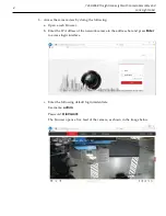
Page 7: ...doing the following a Open a web browser b Enter the IP Address of the network camera in the address bar and press Enter to access login interface c Enter the following default login credentials User...

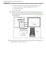
Page 8: ...tomer area is visible Cart area is visible Note Refer to the image below for an example of an ideal camera view For the purpose of illustration only the image below shows a Right hand RH orientation F...

Page 9: ...ane Light assembly follow these steps 1 Turn off the NCR SelfServ Checkout software and hardware systems For more information refer to General Operational Procedures section of NCR SelfServ Checkout 7...

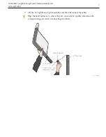
Page 10: ...Camera Assembly and Lane Light Label 7 3 Lift the Tri Light Lane Light assembly and then disconnect the cables Tip Mark all cables as to where they are connected to quickly determine the correspondin...

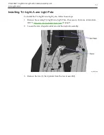
Page 11: ...embly and Lane Light Label Removing Tri Light Lane Light Pole To remove the Tri Light Lane Light Pole follow these steps 1 Insert key in lock on the back of tower and then turn counterclockwise to unl...

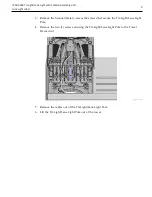
Page 12: ...e the Scanner Scale to access the screws that secure the Tri Light Lane Light Pole 4 Remove the two 2 screws securing the Tri Light Lane Light Pole to the Tower Frame duct 5 Remove the cables out of t...

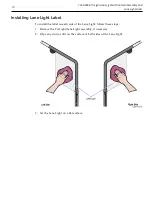
Page 13: ...Label Installing Lane Light Label To install the label on each side of the Lane Light follow these steps 1 Remove the Tri Light Lane Light assembly if necessary 2 Wipe any dust or dirt on the surface...

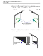
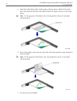
Page 14: ...the type of Lane Light label do either of the following Position the label on the Lane Light Ensure that the label is flush with the front edge of the Lane Light as shown in the image below Position...

Page 15: ...hen attach the label on the Lane Light as shown in the image below Note For the purpose of illustration only the image below shows a Lane Light FastLane label 6 Peel off the adhesive tape from the oth...

Page 16: ...To install the Tri Light Lane Light pole follow these steps 1 Remove the existing Tri Light Lane Light Pole if necessary For more information refer to Removing Tri Light Lane Light Pole on page 8 2 L...

Page 17: ...nder I O Box Tri Light Lane Light port Ethernet LAN cable extender Ethernet LAN I O Box Power cable extender I O Box Input Belt Tip To make routing the cable extender through the pole easier first att...

Page 18: ...ane Light with Camera Assembly and Lane Light Label 15 5 Route the cables coming out of the unit so they align with the grooves and carefully insert the pole into the tower 6 Secure the pole to the to...

Page 19: ...0 K068 Tri Light Lane Light with Camera Assembly and Lane Light Label 7 Insert the excess cables into the opening on the Tri Light Lane Light pole so that the cables will not interfere with any outer...

Page 20: ...teps Note Ensure that the NCR Customer Helpdesk is informed when the Tri Light Lane Light with Camera is installed in the store 1 Remove the existing Tri Light Lane Light assembly if necessary For mor...

Page 21: ...18 7360 K068 Tri Light Lane Light with Camera Assembly and Lane Light Label 3 Connect the Tri Light Lane Light with Camera Assembly cables...

Page 22: ...ane Light Label 19 4 Install three 3 cable ties on each side of the power connector and on the Ethernet cable to provide strain relief as shown in the image below 5 Orient the Tri Light Lane Light ass...

Page 23: ...Tri Light Lane Light pole Ensure that the pole holes are aligned Tip To easily insert the cables with connectors through the pole insert first the LAN cable followed by the Power cable and then the Tr...

Page 24: ...ng the cables refer to Routing Tri Light Lane Light Cable on the next page Tri Light Destination Connection Location Tri Light Lane Light cable extender I O Box Tri Light Lane Light port Ethernet LAN...

Page 25: ...in the Full Recycling Fixed unit follow these steps 1 Do the following a From the Tower Frame pole duct route the Tri Light Lane Light cable down through the built in hooks inside the Tower Frame b R...

Page 26: ...orner cable access hole route the cable down the Core Cabinet wall and connect to the I O Box Tri Light Lane Light port Use cable ties to secure the cable on bridge lances Note For the Tri Light Lane...

Page 27: ...the Tri Light Lane Light with Camera assembly if necessary For more information refer to Installing Tri Light Lane Light with Camera Assembly on page 17 C Install the HikVision Search Active Devices P...

Page 28: ...nding information 3 Modify the network parameters by the doing the following if necessary a Select the camera to modify by checking the check box a Select the arrow on the right side of the interface...

Page 29: ...ine devices For more information about SADP Tool refer to HikVision Tools Download Note Ensure that the camera and the device DVA lane computer or laptop used for configuration are connected to the sa...

Page 30: ...Light with Camera Assembly and Lane Light Label 27 4 Select Next The installation window shows the default destination folder 5 Select Change to enter a different destination from the default destina...

Page 31: ...th Camera Assembly and Lane Light Label 6 Select Next throughout the process to choose all default settings until the window notifies that installation is complete A setup window for Win10Pcap appears...

Page 32: ...Light with Camera Assembly and Lane Light Label 29 7 Select Next The installation window shows the default destination folder 8 Select Change to enter a different destination from the default destinat...

Page 33: ...ight with Camera Assembly and Lane Light Label 9 Select Next to continue The Windows Security Alert appears 10 Select Next to proceed with the installation The SADP Tool icon appears on the desktop on...

Reviews: