background image

O

XI

M

AX

N-600

X

Pulse Oximeter

with

Alarm Management System

Service Manual

TM

To Purchase, Visit 

Avobus.com

 or call 

1-800-674-3655

Summary of Contents for OXIMAX N-600X Series

Page 1: ...OXIMAX N 600X Pulse Oximeter with Alarm Management System Service Manual TM To Purchase Visit Avobus com or call 1 800 674 3655...

Page 2: ...35 223 6 226 539 6 411 833 6 463 310 6 591 123 6 708 049 7 016 715 7 039 538 7 120 479 7 120 480 7 142 142 7 162 288 7 190 985 7 194 293 7 209 774 7 212 847 To obtain information about a warranty if a...

Page 3: ...ions 21 Oximeter Features 22 OxiMax SPD Alert Feature 22 SatSeconds Alarm Management Feature 22 Pulse Rate Delay Alarm Management Feature 26 Oximeter Display View Options 26 Selecting Display Views 26...

Page 4: ...r Features 41 SatSeconds Alarm Management Feature 41 Pulse Rate Delay Alarm Management Feature 41 OxiMax SPD Alert Feature 42 OxiMax Pulse Oximetry Sensor Technology 42 Functional Testers and Patient...

Page 5: ...enu Options 64 Adjusting the Factory Default Settings 72 Using the OxiMax SPD Alert Feature 77 Using the Pulse Rate Delay Alarm Management Feature 78 Using the SatSeconds Alarm Management Feature 78 C...

Page 6: ...afety Testing Standards 106 Battery Check 106 Battery Power 106 Battery Charge 106 Performance Tests 107 Power On Defaults and Alarm Ranges 107 Operational Setup 110 Overall Performance Check 115 Puls...

Page 7: ...le 173 Power Supply Replacement 174 Removing the Power Supply 174 Replacing the Power Supply 175 Cooling Fan Replacement 176 Removing the Cooling Fan 176 Replacing the Cooling Fan 176 Display PCB Repl...

Page 8: ...viii 10030881 Rev B 12 2008 Service Manual...

Page 9: ...essary for the safe and effective use of the OxiMax N 600x pulse oximeter Notes are identified by the NOTE symbol shown above Notes are listed before or after procedural steps or information and provi...

Page 10: ...e chassis since this may cause damage to the oximeter WARNING Supplemental oxygen will attenuate patterns of desaturation A patient s respiratory compromise can be proportionally more severe before pa...

Page 11: ...er to any instrument verify proper operation before clinical use Both the pulse oximeter and the instrument connected to it must utilize a grounded outlet Accessory equipment connected to the pulse ox...

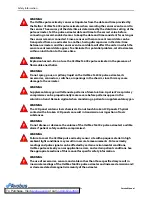
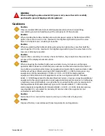
Page 12: ...Safety Information 12 10030881 Rev B 12 2008 Service Manual...

Page 13: ...you with a basic understanding of the OxiMax N 600x pulse oximeter principles of operation This knowledge is essential in performing tests and using circuit analysis sections to maintain the oximeter...

Page 14: ...and in hospital type facilities Hospital type facilities include physician office based facilities sleep labs skilled nursing facilities surgicenters and sub acute centers Intra hospital transport inc...

Page 15: ...tents Table 1 Typical Packing List Quantity Item 1 OxiMax N 600x pulse oximeter 1 Nellcor OxiMax pulse oximetry sensor or assortment pack 1 DOC 10 pulse oximetry cable 1 N 600x Operator s Manual appli...

Page 16: ...larm volume The ALARM SILENCE key clears SENSOR OFF LOW BATTERY and SENSOR DISCONNECT Table 2 List of Front Panel Components 1 SpO2 Sensor Port 14 ADJUST UP DOWN Keys 2 Low Battery Indicator 15 Pulse...

Page 17: ...ftkey menu functions Oximeter Visual Indicators AC Power Indicator Lights continuously when connected to an AC power source and also shows when the battery is charging Does not light when the oximeter...

Page 18: ...ing loss of pulse alarms and when the pulse rate is outside of the alarm limits During Pulse Search the oximeter continues to update the display Pulse rates outside of the pulse rate range of 20 to 25...

Page 19: ...limit values but not when set to adult limit values For more information about using the feature reference the N 600x Operator s Manual Monitoring Values WARNING Failure to cover the OxiMax pulse oxim...

Page 20: ...m Priority Alarm Medium pitched pulsing tone indicates an SpO2 or pulse rate limit violation Note If a Medium Priority Alarm is not silenced within two minutes by pressing the ALARM SILENCE key the ox...

Page 21: ...ions Warning See Instructions for Use Fuse replacement Equipotential terminal ground Date of manufacture Data interface Proper WEEE Waste Disposal Type BF applied part Not defibrillator proof Table 4...

Page 22: ...qualifies patterns of desaturation resulting from such repetitive reductions in airflow based on specific characteristics The severity of the desaturation event the depth of the desaturation during t...

Page 23: ...s both degree and duration of desaturation as an index of desaturation severity Thus the SatSeconds feature helps distinguish clinically significant events from minor and brief desaturations that may...

Page 24: ...General Introduction 24 10030881 Rev B 12 2008 Service Manual Figure 6 Second Event No SatSeconds Alarm...

Page 25: ...n levels frequently below the limit but not staying below the limit long enough for the SatSeconds time setting to be reached When three or more limit violations occur within 60 seconds an alarm sound...

Page 26: ...e Rate Delay limit controls the time the pulse rate level crosses either limit before an audible alarm sounds Reference Oximeter Display View Options page 26 Managing the View Display page 62 Using th...

Page 27: ...0x Operator s Manual Blip Display Figure 10 Blip Display View Use this display view for visual monitoring information in blip bar form The blip display includes a pulse amplitude blip bar current meas...

Page 28: ...d pulse rates It also includes a battery fuel gauge if running on battery power Each time the oximeter detects a pulse the heart icon flashes If enabled SatSeconds and SPD icons display For more infor...

Page 29: ...o 240 volts AC nominal 230 VAC 30 VA Input Frequency 50 60 Hz Fuses Slow blow 0 5 amp 250 volts IEC 5 x 20 mm Quantity 2 external Battery Note The battery provides approximately seven hours of battery...

Page 30: ...82 ft Atmospheric Pressure 70 kPa to 106 kPa 20 6 in Hg to 31 3 in Hg Relative Humidity 15 to 95 non condensing Transport and Storage Not in shipping container In shipping container Temperature 20 C t...

Page 31: ...ng a range of 85 to 99 SaO2 3 Clinical functionality has been demonstrated in a population of hospitalized neonate patients The observed accuracy was 3 0 in a study of 57 patients with ages of 24 to 4...

Page 32: ...I Internally powered Mode of Operation Continuous Liquid Ingress IPX1 Degree of Safety Not suitable for use in the presence of a flammable anaesthetic gas Electromagnetic Compatibility EMC Standards I...

Page 33: ...reflection from structures objects and people Table 6 Electromagnetic Emissions Emissions Test Compliance Electromagnetic Environment Guidance RF emissions CISPR 11 2004 Group 1 Class B The oximeter...

Page 34: ...terruptions and voltage variations on power supply IEC 61000 4 11 2004 5 UT 95 dip in UT for 0 5 cycle 5 UT 95 dip in UT for 0 5 cycle Mains power quality should be that of a typical commercial and or...

Page 35: ...ance WARNING The use of accessories OxiMax sensors and cables other than those specified may result in inaccurate readings of the OxiMax N 600x pulse oximeter and increased emission of the oximeter Ta...

Page 36: ...Non terminated cable RS 232 analog 15 pin D 10 0 ft 3 m Printer cable RS 232 15 to 9 pin D 10 0 ft 3 m Philips interface cable 3 3 ft 1 m Oxinet III hardwire cable 10 0 ft 3 m Oxinet III Data Cable 1...

Page 37: ...IEC 60601 1 UL 60601 1 Normal Normal Closed Closed 500 A 300 A Single Fault Open Closed 1000 A Closed Open Normal Reversed Closed Closed 500 A 300 A Single Fault Open Closed 1000 A Closed Open Enclos...

Page 38: ...ine Power Line Ground Cable IEC 60601 1 UL 60601 1 Normal Normal Closed Closed 100 A Single Fault Open Closed 500 A Closed Open Normal Reversed Closed Closed 100 A Single Fault Open Closed 500 A Close...

Page 39: ...iples oxyhemoglobin and deoxyhemoglobin differ in their absorption of red and infrared light measured using spectrophotometry and the volume of arterial blood in tissue and hence light absorption by t...

Page 40: ...al operation and does not require any user intervention Functional versus Fractional Saturation This pulse oximeter measures functional saturation where oxygenated hemoglobin is expressed as a percent...

Page 41: ...stinguishes clinically significant events from minor and brief SpO2 limit violations that result in nuisance alarms Set upper and lower alarm limits using traditional alarm management methods Then use...

Page 42: ...r the SPD triangle icon Refer to Using the OxiMax SPD Alert Feature page 77 for detecting patterns of desaturation OxiMax Pulse Oximetry Sensor Technology Use OxiMax pulse oximetry sensors which are s...

Page 43: ...operly evaluate the accuracy of a system s SpO2 measurements Fully evaluating the accuracy of the SpO2 measurements requires at a minimum accommodating the wavelength characteristics of the sensor and...

Page 44: ...Theory of Operations 44 10030881 Rev B 12 2008 Service Manual...

Page 45: ...se oximeter relies on unique oximetry technology and design in providing hospitals clinicians and caregivers accurate timely data Oximeter Block Diagram The following block diagram shows the flow of d...

Page 46: ...ve the 823e provides the bulk of the functionality in the oximeter acting as the master controller while NELL 1A Oximetry Module handles the pulse oximetry functions and the Linear Power Supply LPS bo...

Page 47: ...provides various display capabilities including numeric readouts for SpO2 and beats per minute BPM pulse rate graphical pleth wave and pulse blip bar menu selection elements and status error messages...

Page 48: ...for Use DFU and the OxiMax Sensor Accuracy Grid SAG Also reference the Product Specifications chapter for Pulse Oximetry Sensor Accuracy page 31 The NELL 1A oximetry module drives the sensor s LEDs c...

Page 49: ...MRI equipment Also induced currents could potentially cause burns WARNING To ensure accurate performance and prevent device failure do not subject the OxiMax N 600x pulse oximeter to extreme moisture...

Page 50: ...ther equipment If adjacent or stacked use is necessary observe the oximeter to verify normal operation in the desired configuration Note The OxiMax N 600x pulse oximeter incorporates watchdog timers w...

Page 51: ...n immediately Caution If the battery has been in storage for longer than six months or if the battery does not fully recharge the battery should be replaced After the battery has been replaced and a n...

Page 52: ...rst recharge in several weeks 1 Connect the oximeter to an AC power source The oximeter will not power up without connection to AC power 2 Verify the oximeter is off and the AC Power Battery Charging...

Page 53: ...OxiMax pulse oximetry sensor to the oximeter or when the oximeter completes POST with an OxiMax pulse oximetry sensor attached Note Physiological conditions medical procedures or external agents that...

Page 54: ...high definition television it is possible that high levels of such interference due to close proximity or strength of a source may result in disruption of N 600x pulse oximeter performance The OxiMax...

Page 55: ...unctional damage contact Nellcor s Technical Services Department at 1 800 635 5267 or your local Nellcor representative Monitoring Oximeter Power Battery Fuel Gauge Any time the oximeter is not connec...

Page 56: ...ly results in a low priority alarm and a lighted low battery indicator Ensure that the switch setting matches your AC voltage The Low Battery Indicator lights and a low priority alarm begins to sound...

Page 57: ...lt display With a sensor cable and an OxiMax pulse oximetry sensor attached the unit is ready to register and record patient trend data Power up performance tests verify both power on self test POST a...

Page 58: ...wo seconds c The LCD display should show the NELLCOR logo and the firmware version of the OxiMax N 600x pulse oximeter 5 Observe the LCD screen for the POST splash screen which displays for approximat...

Page 59: ...ring agents such as nail polish dye or pigmented cream Automatic Shutdown and Power Off Automatic Shutdown When all of the following conditions are present for 15 minutes the OxiMax N 600x pulse oxime...

Page 60: ...s the type model of pulse oximetry sensor connected to the oximeter The type is used to determine the action messages in the sensor message s function For a pulse oximetry sensor containing data the m...

Page 61: ...signal condition screen The poor signal condition screen is part of the Sensor Messages feature Figure 21 Poor Signal Condition Message Sensor Detection Failure Upon successful completion of the POST...

Page 62: ...g the oximeter or manually selecting another view Adjusting the Volume of Audible Tones Adjusting the Pulse Beep Volume The pulse beep emits its tone with each real time event based on data received f...

Page 63: ...nce Duration Screen 2 Press and hold the ALARM SILENCE key and the ADJUST UP key below the ALARM SILENCE key on the oximeter panel to increase the alarm silence duration setting 3 Press and hold the A...

Page 64: ...meter alarm limits are configured to the monitored patient 2 Disconnect the sensor from the oximeter 3 Press the ALARM SILENCE key to silence the audible alarms 4 Press the ALARM SILENCE key to disabl...

Page 65: ...thod of viewing oximeter trend and sensor data Note In the case of a SatSeconds or an SPD event the oximeter proceeds straight to the MONITR menu Clear any alarm condition s to access the TREND menu 3...

Page 66: ...DULT softkey Use this softkey to set upper and lower limits for adult and pediatric patients Scroll through each limit setting option using the SELECT softkey until you reach the limit value you wish...

Page 67: ...AMP amplitude Menu This is an arbitrary unit of measure gauging the distance from the peak to the valley of a pulse waveform The trend data when set to PAU can register amplitudes up to 200 PAU b ZOO...

Page 68: ...isplay c TREND Menu Access trend data display Similar to MONITR trend view menu option VIEW softkey Display sensor trend data Isolate oxygenation SpO2 Option or pulse PULSE Option trend data or viewin...

Page 69: ...the normal monitoring mode press the SETUP softkey 2 Press the NEXT softkey 3 Press the CLOCK softkey 4 Press the SET softkey 5 Press the SELECT softkey to select the TIME and DATE fields as shown TI...

Page 70: ...press the NEXT softkey Use the SELECT softkey to toggle between the baud rate and communication protocol Arrow up or down to select the proper baud rate Baud rates include 19200 9600 and 2400 baud fo...

Page 71: ...response mode however may impact the SPD alarm behavior From the SETUP menu press the NEXT softkey twice to reach the MODE menu option a Normal Mode Default response mode responds to changes in blood...

Page 72: ...appropriate for the patient being monitored WARNING The SPD feature is for use with adults patients only In Neonate Mode the SPD feature remains OFF Caution Use of the SPD alarm feature does not chang...

Page 73: ...e either of these values as default results in an invalid tone These limits can be adjusted lower for the current patient but return to power on defaults at power off Note The SPD feature automaticall...

Page 74: ...Contrast Midrange Display Format GCF Backlight Brightness 8 Battery Power 10 AC Power Language English Pulse Beep Volume 4 of 10 Pulse Rate Lower Alarm Limit 40 BPM 90 BPM Pulse Rate Upper Alarm Limi...

Page 75: ...IMITS or NEONATE LIMITS screen based on institutional or default settings a The adult limits screen displays the institutional or factory default settings appropriate to adult and pediatric patients F...

Page 76: ...fect as long as the oximeter power continues but return to the institutional default limits when oximeter power is turned off Only qualified service personnel may change factory defaults to institutio...

Page 77: ...eter is to patterns of desaturation The default setting of one 1 is the most sensitive Note When SPD is enabled the SatSeconds feature is automatically enabled with a setting of 100 Note The ability t...

Page 78: ...econds alarm limit To adjust the SatSeconds limit select the adult or neonate alarm limit display Note The ability to adjust the SatSeconds Alarm limit default settings can be enabled or disabled by q...

Page 79: ...utput port configures a medical system and is therefore responsible for ensuring the system complies with Requirements for Medical Electrical Systems IEC Standard 60601 1 1 2000 and the electromagneti...

Page 80: ...9 of the cable and keep cable length to a maximum of 4 000 feet Plug the end of the cable with the resistor added into the oximeter Differential Data Transmission Pins 3 and 4 TxD and TxD are the diff...

Page 81: ...Output page 88 Holding the Ctrl key on the computer keyboard and pressing C twice accesses an interactive mode Activating the interactive mode halts the real time serial output while accepting serial...

Page 82: ...ludes instrument type software revision level printout type time of printout operating time of the recorded error error number task number address and count 5 Exit Interactive Mode Closes the interact...

Page 83: ...ADJUST UP or ADJUST DOWN softkeys below the ALARM SILENCE key on the oximeter panel to select the desired baud rate should it differ from the default for that particular protocol 8 Press the EXIT soft...

Page 84: ...d pulse amplitude as well as providing a remote nurse call function The OxiMax N 600x pulse oximeter provides a bedside oximeter communication for interfacing with Philips monitors Adjust data port op...

Page 85: ...Press the SETUP softkey 3 Press the NEXT softkey twice 4 Press the COMM softkey 5 Press the SELECT softkey 6 Use the ADJUST UP and ADJUST DOWN buttons to select the desired protocol 7 Press the EXIT...

Page 86: ...ate to 19200 bits per second bps Managing the Data Port Data Printout Information Printing Oximeter Trend Data Trend information oximeter and in sensor event history can be sent to a personal computer...

Page 87: ...79 8 Press the EXIT softkey 9 Enter the Service Menu by simultaneously pressing and holding the LIGHT softkey and the HELP CONTRAST button until the service softkeys display Figure 43 PARAM and PRINT...

Page 88: ...data can be obtained through the data port by connecting the oximeter data port to a PC or serial printer When a real time printout or display is being transmitted to a printer or PC a new line of dat...

Page 89: ...a column heading changes The example above shows three distinct column heading sets Starting at the top row there are 25 lines before the second row of column headings print The third row of column he...

Page 90: ...or is 85 and the upper alarm limit is 100 Pulse Rate alarm limits are 40 and 170 bpm The SatSeconds alarm limit 100SAT S displays the SatSeconds alarm setting In this example SatSeconds is set to 100...

Page 91: ...A represents the pulse amplitude value in which the number can range from 0 to 254 There are no alarm parameters for this value It can be used for trending information as an indication of a change in...

Page 92: ...t SPD setting options a SPD Sensitivity Setting Establishes a threshold at which patterns of desaturation trigger an alarm Very Sensitive The default setting of one 1 is very sensitive to desaturation...

Page 93: ...e call interfaces an RS 232 level and relay closure The RS 232 level nurse call function operates when the oximeter is connected to AC power or on battery The relay based nurse call function is availa...

Page 94: ...condition or a negative signal NORM on a oximeter alarm condition To set nurse call polarity 1 With the oximeter in the normal monitoring mode press the SETUP softkey 2 Press the NEXT softkey twice an...

Page 95: ...aries proportionally from 0 0 to 1 0 VDC as the pin s parameter varies over its full range of values For example as the current value of SpO2 varies from 0 to 100 the voltage from pin 6 to ground pin...

Page 96: ...Managing the Data Port 96 10030881 Rev B 12 2008 Service Manual...

Page 97: ...technician should perform these procedures prior to initial installation in a clinical setting Performance Considerations Primary Considerations Application issues and certain patient conditions can...

Page 98: ...patient may be hypoxic Correcting anemia can improve arterial oxygen content The oximeter may fail to provide an SpO2 reading if hemoglobin levels fall below 5 gm dl OxiMax Pulse Oximetry Sensor Perf...

Page 99: ...ate OxiMax pulse oximetry sensor apply it as directed and observe all warnings and cautions presented in the directions for use accompanying the sensor Clean and remove any substances such as nail pol...

Page 100: ...nges to the SpO2 up to 60 seconds earlier than digit sensors If the Max Fast pulse oximetry sensor is not available consider using the OxiMax Max R adhesive nasal sensor It obtains extremely accurate...

Page 101: ...Disinfection Use a soft cloth saturated with a solution of 10 chlorine bleach in tap water lightly wiping the surface of the oximeter Before attempting to clean an OxiMax pulse oximetry sensor read t...

Page 102: ...ectrical safety tests detailed in Modifying and Testing the Oximeter page 103 If the unit fails the tests refer to Ordering Oximeter Spare Parts page 161 2 Inspect the external fuses for proper value...

Page 103: ...alues using the oximeter s service mode Set temporary desired limits in normal operation mode Table 19 Institutional Default Settings Parameter Possible Setting Alarms Allow Off Yes No Alarm Volume 1...

Page 104: ...usting the Factory Default Settings page 72 for parameter values 3 Simultaneously press the LIGHT softkey and the HELP CONTRAST button until the softkey headings appear 4 Press the PARAM softkey Figur...

Page 105: ...to the caregiver If the pulse oximeter fails to perform as specified in any test make all repairs necessary to correct the problem before returning the oximeter to the caregiver Required Equipment Tab...

Page 106: ...nector with all pins shorted together During these tests the oximeter displays the following message RECONNECT REPLACE SENSOR Battery Check Note Replace the battery every 24 months Battery Power To ch...

Page 107: ...ctory settings or defaults set by the institution Note The descriptions below are based on the default GCF view with SatSeconds and the Saturation Pattern Detection SPD feature enabled The steps for c...

Page 108: ...the oximeter emits a single beep and the SpO2 Lower Alarm Limit of 85 or the institutional default setting is selected Figure 66 Testing Adult SpO2 Lower Limits 6 Press and hold the ADJUST DOWN button...

Page 109: ...pper Alarm Limit display indicates an alarm limit of 100 18 Verify the SpO2 Lower Alarm Limit display indicates an alarm limit of 85 Testing SatSeconds Saturation Pattern Detection and Pulse Rate Dela...

Page 110: ...h 5 10 and back to OFF Figure 71 Testing Pulse Rate Delay Thresholds 12 Press the ON STANDBY button to turn the oximeter off 13 Press the ON STANDBY button to turn the oximeter back on 14 Press the LI...

Page 111: ...e oximeter on 4 Press SETUP and then VIEW 5 Press the PLETH softkey Verify the SpO2 and BPM indicate the SpO2 and pulse rate 6 Press the LIMITS softkey 7 Press the SELECT softkey to select SpO2 Lower...

Page 112: ...120 appears in the SpO2 display Figure 76 ALARM SILENCE setting of 120 seconds 14 Press the ALARM SILENCE button 15 With the oximeter s alarm silenced verify the following a Alarm remains silenced for...

Page 113: ...duration perform the following alarm volume test procedure Note The alarm mode is still set to OFF unless the oximeter has been power cycled when default settings are reinstated To test the alarm volu...

Page 114: ...ing the ADJUST DOWN button to a comfortable audio level 5 Release the ALARM SILENCE button The tone discontinues Pulse Tone Volume Control Adjust the pulse tone volume after adjusting the Alarm Volume...

Page 115: ...more than two minutes to complete the analog output times out Repeat steps 2 through 6 to initiate the analog output 7 Move the positive lead back to pin 6 8 Press the SETUP softkey 9 Press the NEXT s...

Page 116: ...put cable 4 Press the ON STANDBY button to turn the oximeter on 5 Leave the Max A pulse oximetry sensor open with the LEDs and photo detector visible 6 After the oximeter completes a normal power on s...

Page 117: ...nect the DS 100A pulse oximetry sensor to the DOC 10 pulse oximetry cable 4 Attach the sensor to a live subject as recommended in the OxiMax pulse oximetry sensor s Directions For Use 5 Press the ON S...

Page 118: ...OxiMax Oximetry Tester Overview The SRC MAX functional tester enables qualified technicians to functionally test Nellcor OxiMax technology based oximeters and OEM OxiMax technology based Table 21 SRC...

Page 119: ...ximetry cable to the sensor port 2 Connect the SRC MAX tester to the other end of the DOC 10 cable 3 Turn on the oximeter by pressing the ON STANDBY button Wait for the oximeter to complete its self c...

Page 120: ...ch peak to peak P T P amplitude Actual amplitude may vary but will be a reference for low pulse amplitude low light patients 5 Press the SRC MAX PULSE RATE selection button The SRC MAX PULSE RATE 200...

Page 121: ...O2 Test 1 With the oximeter turned off connect the DOC 10 pulse oximetry cable to the sensor port 2 Connect the SRC MAX tester to the other end of the DOC 10 cable 3 Turn on the oximeter by pressing t...

Page 122: ...s the SRC MAX SpO2 selection button The SRC MAX SpO2 75 LED lights The oximeter displays three dashes until stabilizing at a value between 73 and 77 inclusive Figure 89 PLETH Display with SRC MAX decr...

Page 123: ...Actual amplitude may vary but will be a reference for low pulse amplitude low light patients 5 Press the SRC MAX MODULATION selection button The SRC MAX MODULATION LED lights The oximeter pulse amplit...

Page 124: ...P T P amplitude Actual amplitude may vary but will be a reference for high pulse amplitude low light patients 7 Press the SRC MAX PULSE RATE selection button The SRC MAX PULSE RATE 60 LED lights The...

Page 125: ...ximately 1 inch P T P amplitude Actual amplitude may vary but can be used as a reference for high pulse amplitude low light patients 9 Press the SRC MAX SpO2 selection button The SRC MAX SpO2 75 LED l...

Page 126: ...off the oximeter Light Level Test 1 With the oximeter turned off connect the DOC 10 pulse oximetry cable to the sensor port 2 Connect the SRC MAX tester to the other end of the DOC 10 cable 3 Turn on...

Page 127: ...7 and 63 inclusive d Pulse waveform of approximately 1 2 inch P T P amplitude Actual amplitude may vary but can be used as a reference for low pulse amplitude high light patients 6 Press the SRC MAX P...

Page 128: ...Pulse waveform of approximately 1 2 inch P T P amplitude Actual amplitude may vary but can be used as a reference for low modulation high light indications 8 Press the SRC MAX SpO2 selection button Th...

Page 129: ...ly 1 2 inch P T P amplitude Actual amplitude may vary but can be used as a reference for low modulation high light indications 10 Press the SRC MAX MODULATION selection button The SRC MAX MODULATION L...

Page 130: ...the RS 232 Nurse Call function by simulating an alarm condition 8 With oximeter in an alarm condition use a digital voltmeter DVM to ensure there is no continuity 1 megohms or greater between pins 8 a...

Page 131: ...1 SELECT Softkey SELECT the desired function 2 NEXT Softkey Access additional options for the Service Functions Menu by pressing the NEXT softkey 3 BACK Option Return back to the SERVICE Main Menu 4 E...

Page 132: ...saved values continue to be used through power on and off cycles until they are changed and saved again or until they are reset Pressing NO restores the original default values Note An invalid tone in...

Page 133: ...ical engineer In the INSTAT printout line one is for oximeter type software revision level type of printout and alarm parameter settings The second line contains the column headings A trend point is r...

Page 134: ...caregivers the alarm is off by enabling this feature or choose to disable the reminder Enable or disable a SatSeconds reminder Press BACK to return to the Service Menu WARNING Audible alarms should n...

Page 135: ...JUST DOWN buttons can be used to change the choice from YES to NO Selecting YES enables the Reminder Selecting NO disables the Reminder when the audible alarm is set to OFF SPD Setup This option is on...

Page 136: ...Modifying and Testing the Oximeter 136 10030881 Rev B 12 2008 Service Manual To Purchase Visit Avobus com or call 1 800 674 3655...

Page 137: ...ease contact Nellcor s Technical Services or your local Nellcor representative WARNING Do not spray pour or spill any liquid on the OxiMax N 600x pulse oximeter its accessories connectors switches or...

Page 138: ...ion detects repetitive patterns of desaturation in the trend in adults Caregivers are alerted to these patterns via a visual indicator and optionally an audio alarm The triangle icon for Saturation Pa...

Page 139: ...outside the limit and time the number of seconds the SpO2 the value remains outside the limit The SatSeconds limit sets the minimum value the SatSeconds must reach before an alarm is reported For exam...

Page 140: ...TS NEO window appears Figure 116 Neonate Limits Help Screen 7 Press BACK 8 Press ADJUST DOWN t to highlight ADULT and the press SHOW The HELP LIMITS ADULT window appears Figure 117 Adult Limits Help S...

Page 141: ...he time out setting is NONE If the message has a maximum time to remain on the screen it will have a time out setting Note Pressing the ALARM and or ALARM SILENCE keys clears some messages Pressing th...

Page 142: ...0 Yes Yes When pressing and holding the HELP CONTRAST key To adjust the contrast use the ADJUST UP to increase the contrast or ADJUST DOWN key to decrease contrast CLOCK SETTING LOST None No No If the...

Page 143: ...places the failing speaker INVALID SILENCE DURATION 3 No Yes When attempting to save current settings as power on defaults even though the ALARM SILENCE duration is OFF If attempting to save defaults...

Page 144: ...or revert back to the original factory default settings by selecting YES SAVE DEFAULTS 10 No Yes When attempting to save current settings as power on defaults by pressing SAVE in the PARAMS menu Confi...

Page 145: ...re lost Reenter the date and time Recharge or replace the battery 515 518 534 535 569 N 600x Boot Version x x x x The application software is missing or corrupt Notify a qualified service technician 5...

Page 146: ...ront end reported a bad Cyclic Redundancy Check CRC 4 SpO2 front end reported FSP message not allowed 5 SpO2 front end reported illegal value sent in FSP message SpO2 front end 6 SpO2 front end report...

Page 147: ...end reports parameter value out of range 268 SpO2 back end reports reset detected 269 SpO2 back end reports unexpected value 270 SpO2 back end reports time out 271 SpO2 back end reports not ready not...

Page 148: ...ne has received an unknown state transition 523 The operation just attempted was not completed successfully for example Institutional Defaults could not be reset 524 An unexpected value was received f...

Page 149: ...Trend data corrupted 576 LPS Logic Processing Board LPS is going through excessive resets 577 LPS status messages not arriving in a timely manner 578 LPS driver has received too many corrupt protocol...

Page 150: ...SpO2 front end lost 663 Oximetry module reports internal register modified from expected value 701 POST POST external hardware failsafe circuit error 702 POST PWR_ENA fail 703 Unknown state machine o...

Page 151: ...ithout AC power 731 EEPROM EEPROM CRC Error EEPROM cleared 732 Vref Vref error on DC 733 Vref error on AC 734 Temp Overtemperature 58 C 735 Battery Battery I charge 736 Battery I discharge 737 Temp Te...

Page 152: ...n Board PCB Replacement page 179 If the connection is good replace the Main Board PCB The oximeter generates an error code when disconnected from AC power and the oximeter is powered up The battery ma...

Page 153: ...e the Main Board printed circuit board See Main Board PCB Replacement page 179 Display pixels do not light Check the connection between the Main Board PCB and the Display PCB If the condition continue...

Page 154: ...d pad as close to the surgical site as possible and as far away from the OxiMax pulse oximetry sensor as possible Verify the performance with the procedures detailed in Operating the Oximeter page 55...

Page 155: ...ximeter also sounds the piezo tone to annunciate low medium and high priority alarms during this time An OxiMax N 600x pulse oximeter powered off while reporting a primary speaker failure cannot be po...

Page 156: ...RY LED off LOW BATTERY message off Audible alarm off Error code none Effect of ALARM SILENCE key normal Shutdown N A 3 No Yes No SpO2 normal AC Battery charge LED off LOW BATTERY LED on LOW BATTERY me...

Page 157: ...tions Problem Resolution There is no response when I press the ON STANDBY key Ensure the supply voltage selector switch is set to the proper voltage A fuse may be malfunctioning Notify a qualified ser...

Page 158: ...or try another type of OxiMax pulse oximetry sensor Interference may be preventing the oximeter from tracking the pulse Verify the OxiMax pulse oximetry sensor is securely applied and replace it if ne...

Page 159: ...s in the oximeter display each time the oximeter successfully completes the power on self test Write the number down and have it available whenever requesting technical assistance Returning your Oxime...

Page 160: ...Troubleshooting 160 10030881 Rev B 12 2008 Service Manual To Purchase Visit Avobus com or call 1 800 674 3655...

Page 161: ...in Exploded View Figure 123 on page 162 This manual is available on the Internet at http www nellcor com serv manuals aspx Ordering Replacement Parts Nellcor s Technical Services provides technical as...

Page 162: ...2008 Service Manual Spare Parts List The figure below shows the OxiMax N 600x pulse oximeter expanded view See the Spare Parts List by Call out Number page 163 for descriptions and part numbers Figure...

Page 163: ...006091 6 Fuse Drawer 691500 7 Fuses 691032 8 Power Entry Module 10004406 9 Cooling Fan 10003713 10 Power Supply Board or LPS PCB SP10017371 Alarm Speaker not shown SP10003280 Rubber Feet not shown 4 0...

Page 164: ...2 Fuses 6 691500 Fuse Drawer 901863 Power Cord U K not shown 9 10003713 Cooling Fan 10002385 GCX Rollstand not shown Includes basket and handle but not adapter plate 10002622 GCX Mounting Plate not sh...

Page 165: ...hin the unit OxiMax N 600x pulse oximeter major component parts include all PCBs and subassemblies PCBs Battery Cables Chassis enclosures Collect the following tools prior to any disassembly of the ox...

Page 166: ...business reply card After receiving the spare parts please complete and return the business reply card Fuse Replacement To replace external fuses 1 Turn the oximeter off by pressing the ON STANDBY but...

Page 167: ...oximeter repairs when possible To disassemble the oximeter 1 Turn the oximeter off by pressing the ON STANDBY button 2 Disconnect the oximeter from the AC power source 3 Set the oximeter upside down o...

Page 168: ...osure is lying flat on the work surface 8 Place the two halves of the oximeter on the static free work surface 9 Disconnect the oximeter s power supply harness from J200 3 located on the Main Board pr...

Page 169: ...aution Do not pinch any wires between the cases when reassembling the oximeter Before installing the screws inspect the entire edge of the union for even seating 3 Grasp both halves gently rotating it...

Page 170: ...67 4 Remove the two screws from the battery bracket and lift the battery out of the bottom case as shown 5 Be sure to note the polarity of the leads Use needle nose pliers to disconnect the leads from...

Page 171: ...the battery The red wire connects to the positive terminal and the black wire connects to the negative terminal 3 Insert the new battery into the bottom case with the negative terminal towards the ou...

Page 172: ...eps outlined in Disassembling the Oximeter page 167 3 Push the top of the Power Entry Module PEM in from the outside of the case and lift up 4 Use needle nose pliers to disconnect the leads from the P...

Page 173: ...ing the Power Entry Module page 172 2 Install the PEM in the bottom case with the fuse drawer facing down A tab in the bottom case holds the PEM in place 3 Insert the bottom wing of the PEM between th...

Page 174: ...outside of the case and lift up 4 Use needle nose pliers to disconnect the three leads from the PEM shown in Removing the Power Entry Module page 172 5 Disconnect the fan wire harness from J1 1 on the...

Page 175: ...ply and tighten 4 Connect the fan harness to J1 on the power supply 5 Install the PEM in the bottom case with the fuse drawer facing down A tab in the bottom case holds the PEM in place 6 Insert the b...

Page 176: ...ed in Disassembling the Oximeter page 167 3 Disconnect the fan wire harness from J1 1 on the Power Supply PCB as shown 4 Lift the cooling fan from the slots in the bottom case Figure 130 Removing the...

Page 177: ...bstances To remove the Display PCB 1 Turn the oximeter off by pressing the ON STANDBY button 2 Disconnect the oximeter from the AC power source and follow the steps outlined in Disassembling the Oxime...

Page 178: ...Slide the Display PCB into the grooves in the top case 3 Ensure the Display PCB is firmly seated in the top case 4 Apply pressure between the top case and the Display PCB to make good contact with th...

Page 179: ...g the Display PCB Figure 131 on page 177 4 Use a small blade screwdriver to open the clip from either edge of J7 then disconnect the Display PCB ribbon cable from the connector 5 Disconnect the keypad...

Page 180: ...ell of J2 Removing the Display PCB Figure 131 on page 177 on the Main Board PCB until it clicks into place 4 Insert the keypad ribbon cable into J2 on the Main Board PCB 5 Slide the outer shell of J2...

Page 181: ...r disposal of the original speaker assembly To remove the alarm speaker 1 Turn the oximeter off by pressing the ON STANDBY button 2 Disconnect the oximeter from the AC power source and follow the step...

Page 182: ...assembly so it will not be mixed with its replacement Replacing the Alarm Speaker To replace the alarm speaker WARNING Do not allow other metal objects to come into contact with the speaker permanent...

Page 183: ...utlined in Disassembling the Oximeter page 167 3 Follow the steps outlined in Main Board PCB Replacement page 179 Replacing the Top Case Assembly Caution When installing the Main Board PCB hand tighte...

Page 184: ...cal Services Department for a returned goods authorization number RGA 2 Pack the oximeter in a shipping carton by one of two methods a Original Carton Pack the oximeter in its original shipping carton...

Page 185: ...ckaging Figure 134 Packing 2 Place in shipping carton and seal the carton with packing tape 3 Label the carton with a shipping address return address and RGA number if applicable Using a Generic Carto...

Page 186: ...ping carton with a bursting strength of at least 200 lbs per square inch psi 3 Fill the bottom of the carton with at least two inches of packing material 4 Place the bagged unit on the layer of packin...

Page 187: ...rcuitry 6 Main Power Supply Power Control and Check circuitry 7 Display Interface circuitry 8 Battery backed Trend RAM LED Drivers and I O Decode circuitry 9 FE102 Isolated Power Supply circuitry 10 F...

Page 188: ...Oximeter Schematics 188 10030881 Rev B 12 2008 Service Manual Main PCB Schematic Sheet 1 of 13...

Page 189: ...Service Manual 10030881 Rev B 12 2008 189 Main PCB Schematic Sheet 2 of 13...

Page 190: ...Oximeter Schematics 190 10030881 Rev B 12 2008 Service Manual Main PCB Schematic Sheet 3 of 13 To Purchase Visit Avobus com or call 1 800 674 3655...

Page 191: ...Service Manual 10030881 Rev B 12 2008 191 Main PCB Schematic Sheet 4 of 13...

Page 192: ...Oximeter Schematics 192 10030881 Rev B 12 2008 Service Manual Main PCB Schematic Sheet 5 of 13...

Page 193: ...Service Manual 10030881 Rev B 12 2008 193 Main PCB Schematic Sheet 6 of 13 To Purchase Visit Avobus com or call 1 800 674 3655...

Page 194: ...Oximeter Schematics 194 10030881 Rev B 12 2008 Service Manual Main PCB Schematic Sheet 7 of 13...

Page 195: ...Service Manual 10030881 Rev B 12 2008 195 Main PCB Schematic Sheet 8 of 13...

Page 196: ...Oximeter Schematics 196 10030881 Rev B 12 2008 Service Manual Main PCB Schematic Sheet 9 of 13 To Purchase Visit Avobus com or call 1 800 674 3655...

Page 197: ...Service Manual 10030881 Rev B 12 2008 197 Main PCB Schematic Sheet 10 of 13...

Page 198: ...Oximeter Schematics 198 10030881 Rev B 12 2008 Service Manual Main PCB Schematic Sheet 11 of 13...

Page 199: ...Service Manual 10030881 Rev B 12 2008 199 Main PCB Schematic Sheet 12 of 13 To Purchase Visit Avobus com or call 1 800 674 3655...

Page 200: ...Service Manual 10030881 Rev B 12 2008 200 Main PCB Schematic Sheet 13 of 13...

Page 201: ...Service Manual 10030881 Rev B 12 2008 201 Main PCB Assembly Drawing Front View...

Page 202: ...6 AT34 C11 R127 AT174 AT174 C166 AT120 AT356 L5 C99 R180 AT181 AT181 AT380 AT750 C145 C32 R132 C180 C84 AT578 R189 AT476 AT668 AT231 C39 AT205 R48 C75 AT17 AT8 AT510 D16 C106 AT456 C148 AT649 Q1 L15 R...

Page 203: ...3 1 10 12 15 13 8 6 3 1 FAC FAC MAIN_DC MAIN_DC AC AC 0 01U C8 DT1 600V TH I3 W5 W2 W6 W9 W7 W1 E BATT_CHK FAN_CTRL 0 1U C10 100M TH R2 1 4W I2 TP1 1 2W R1 390K TH LINE NEUT_IN LINE_IN EPS2PC3 SW1 TH...

Page 204: ...Oximeter Schematics 204 10030881 Rev B 12 2008 Service Manual...

Page 205: ...Clock 69 Clock Settings Lost 142 145 Communication Philips 85 Confirmation Tone 20 Connecting an OxiMax Sensor 53 Contrast 62 Controls 16 Alarm Silence 16 Help Contrast 17 Cooling Fan Replacement 176...

Page 206: ...Fast Response Mode 19 Low Battery 17 56 Instat Softkey 133 L LED Excitation Test 116 Loss of Pulse 92 Loss of Pulse with Signal Artifact LM 92 Low Battery 92 143 Low Battery Indicator 56 M Main Board...

Page 207: ...83 Removing the Corner Screws 167 Removing the Display PCB 177 Repacking in a Different Carton 185 Repacking in Original Carton 184 Replace Alarm Speaker 182 Battery 171 Cooling Fan 176 Display PCB 17...

Page 208: ...ight 126 Tone Alarm Silence Reminder 20 Confirmation Tone 20 High Priority Alarm 20 Invalid Button Press 20 Low Priority Alarm 20 Medium Priority Alarm 20 Piezo Tone 20 Power On Self Test Pass 20 Puls...

Page 209: ......

Page 210: ...U S A law restricts this device to sale by or on the order of a physician ATTENTION La loi f d rale des tats Unis stipule que ce produit ne peut tre vendu que sur ordre d un m dicin PRECAUCI N La ley...

Reviews: