background image

Part Number: MAN-0047 Rev 12 

July 24, 2009 


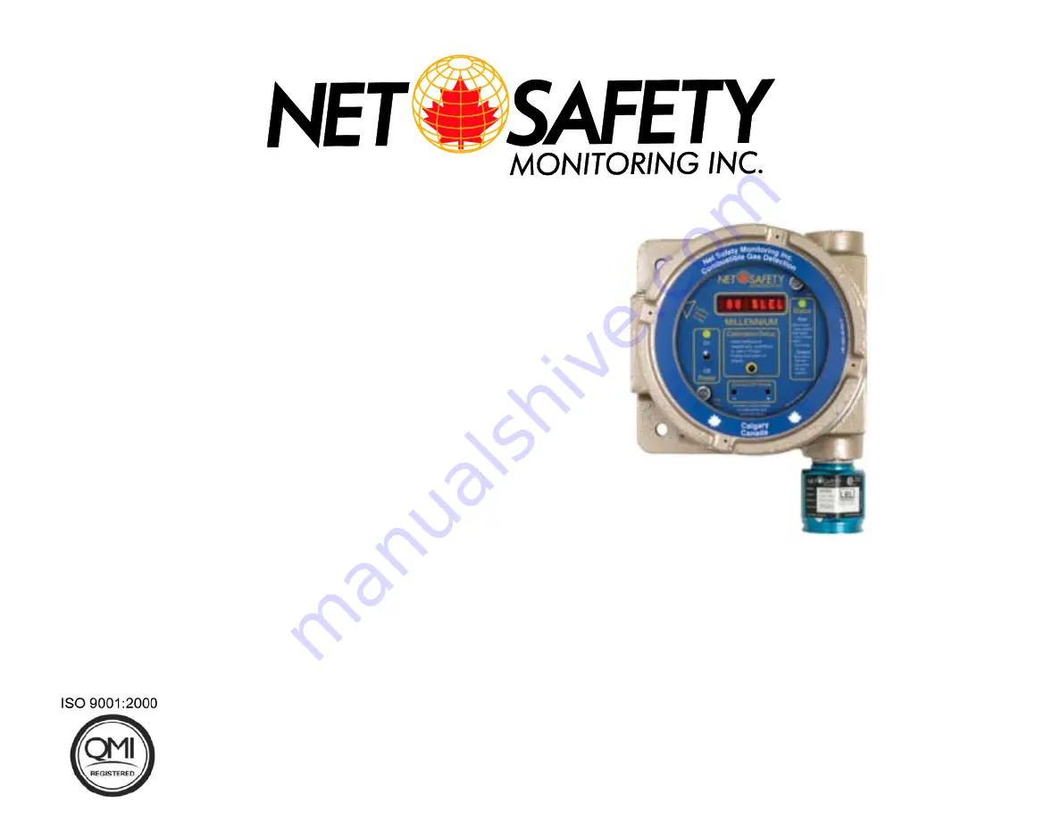
              MILLENNIUM 
   Combustible Gas Detector


                      User Manual 


                            Models: 


MLP-


A/AR/AD-


SC1100 


MLP-


LP-A/AR/ARS


-


SC1100 


Summary of Contents for MLP-A-SC1100

Page 1: ...Part Number MAN 0047 Rev 12 July 24 2009 MILLENNIUM Combustible Gas Detector User Manual Models MLP A AR AD SC1100 MLP LP A AR ARS SC1100...

Page 2: ...ice Each product is thoroughly tested inspected and calibrated prior to shipment Failures can occur which are beyond the control of the manufacturer Failures can be minimized by adhering to the operat...

Page 3: ...RENT OUTPUT 12 NON ISOLATED AND ISOLATED POWER CONFIGURATIONS 13 Remote Reset 13 Modbus Termination 13 SECTION 4 OPERATE 14 Calibration Button 16 Magnetic Reed Switch 16 Power Up 16 Current Loop Measu...

Page 4: ...2 Sensor Guard 23 Reset 23 Manual Reset 23 Remote Reset 23 Outputs 23 Relays Optional 23 Modbus 24 Current 24 SECTION 7 Maintain 24 Periodic Response Check 24 Troubleshoot 24 Table 6 Troubleshooting g...

Page 5: ...n the most severe environments The Controller Transmitter The Millennium Controller has an Explosion Proof Housing rated Class 1 Division 1 Groups B C and D for hazardous applications It was designed...

Page 6: ...gas to be detected Use common sense and refer to the regulatory publications that discuss guidelines for your industry The two most common installations options are as follows Option 1 Locate the sens...

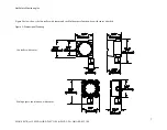
Page 7: ...12 MLP A AR AD SC1100 MLP LP A AR ARS SC1100 Figure 2 below shows the Controller with sensor and the Multipurpose Junction box with sensor attached Figure 2 Dimensional Drawing Multi purpose Junction...

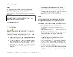
Page 8: ...If you find any components missing or damaged notify the representative or Net Safety Monitoring immediately Figure 3 Components External Equipment It is necessary that reliable monitoring and indica...

Page 9: ...device in the chain requires end of line termination RS 485 connection 2 wire multipoint serial line Seal The use of seals is recommended to further protect the system against any unwanted water ingre...

Page 10: ...chanical Option board and Modbus board These Boards are field replaceable Simply loosen the locking standoffs remove one board insert the other board and tighten screws Depending upon requirements eit...

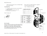
Page 11: ...tart Delay Status LED is Red Slow Flash and current output displays 3 0 mA This is the start up delay sequence which will last approximately 90 seconds Refer to Tables 1and 2 along with Figure 6 for w...

Page 12: ...ment wire minimum 16 AWG should be used for separations up to 150 feet Note Factory default for Sensor Separation is 0 75 feet The actual physical distance between the sensor and controller must be de...

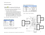
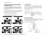
Page 13: ...ource and sink See Figure 7 and Figure 8 Note the Jumper position for each configuration Figure 8 Current Source and Sink Drawing Remote Reset If the Millennium relays are set for latching a remote re...

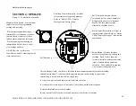
Page 14: ...moval allows access to terminal boards The face plate remains attached to the ribbon cable Status Light flashes Red or Green to indicate status of unit Refer to Status LEDs Display Messages for detail...

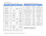
Page 15: ...scale Failed calibration 3 0 3 3 mA Red flash Green flash Fail cal RTU Status Registers and meaning RTUstat_fault 0x0001 Fault sensor RTUstat_low_alarm 0X0002 Low alarm tripped RTUstat_high_alarm 0X0...

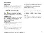
Page 16: ...using the magnet Place and hold the magnet to the Controller s Housing 10 o clock position to calibrate and access Main Menu Briefly place the magnet to the Controller s Housing 10 o clock position to...

Page 17: ...ay followed by the prompt YES 4 To select an option momentarily place the magnet to the Reed Switch or press the Calibration Button at the YES prompt 5 If you do not wish to select that option wait un...

Page 18: ...ean air 7 Wait for Apply 50 Span Gas to display and apply specific LEL gas at a rate of 0 5 litres per minute use 1 0 litre per minute for remote calibration 8 The display will show Calibrating as gas...

Page 19: ...tion Failure If the calibration procedure fails the display shows Fail Cal the Status LED alternates Red Green flashes and the analog output changes back and forth from 3 0 to 3 3 mA The unit remains...

Page 20: ...ss the Calibration Button or use the Reed Switch to select The flashing YES confirms the selection If no selection is made Latch Status option is repeated 7 The message Set High displays The High Alar...

Page 21: ...r Options YES displays press the Calibration Button or use the Reed Switch to select The flashing YES confirms the selection 3 When Lower Display Brightness YES displays press the Calibration Button o...

Page 22: ...event proper response When power is applied the microcontroller automatically tests the system to ensure that it is functioning properly During normal operation it continuously monitors the signal fro...

Page 23: ...ous CSA and ISA require that a reading of at least 60 LEL is reached under such conditions To be safe alarm signals should latch at 60 LEL and require a manual reset action to restore normal operation...

Page 24: ...7 Maintain Periodic Response Check We recommend the Millennium be verified or calibrated every 3 months A typical response check involves the application of calibration gas to the sensor then the obse...

Page 25: ...orrect power supply Replace sensor Correct sensor wiring at controller Correct junction box wiring Contact factory Contact factory Unstable 4 20 mA signal Unshielded cables used for wiring Water invas...

Page 26: ...y Monitoring Inc 2721 Hopewell Place NE Calgary Alberta Canada T1Y 7J7 6 Mark all packages RETURN for REPAIR Waybills for shipments from outside Canada must state Equipment being returned for repair A...

Page 27: ...applications it is necessary for the Millennium Controller to be mounted in a non standard orientation To accommodate such installations and ensure that the display will appear at the correct angle f...

Page 28: ...Assembly 11 Replace faceplate and tighten Pull Here knobs 12 Return power to detector and replace housing cover See Figure 14 PCB Assembly Rotated Figure 14 PCB Assembly Rotated Warning See Appendix E...

Page 29: ...ingly normal for an indefinite period of time followed by a sudden failure To eliminate potential ESD damage review the following guidelines Handle boards by metal shields taking care not to touch ele...

Page 30: ...3 21 2 02 1 27 0 80 0 50 900 9 14 5 75 3 61 2 27 1 43 0 90 0 57 1000 10 20 6 39 4 02 2 53 1 59 1 09 0 63 1250 12 70 7 99 5 03 3 16 1 99 1 25 0 79 1500 15 20 9 58 6 02 3 79 2 38 1 50 0 94 1750 17 80 1...

Page 31: ...0 30 6 50 4 08 7000 71 10 44 70 28 10 17 70 11 10 7 00 4 40 7500 76 10 47 90 30 10 19 00 12 00 7 49 4 71 8000 81 20 51 10 23 10 20 20 12 70 7 99 5 03 9000 91 40 57 50 36 10 22 70 14 30 8 99 5 65 10000...

Page 32: ...ial Powder Coated or Anodized Aluminum optional stainless steel Range of Detection 0 to 100 LEL of most hydrocarbons and hydrogen Accuracy 3 LEL up to 50 LEL 5 LEL above 50 LEL Response Time 10 second...

Page 33: ...er 2ms Operating voltage 10 5 to 32VDC Operating temp range Operational 50 C to 85 C 58F to 185F Certified 40 C to 85 C 40F to 185F Humidity Range 0 to 100 Relative humidity non condensing Powder coat...

Page 34: ...NE Calgary AB Canada T1Y 7J7 1 866 FIREGAS 347 3427 ph 403 219 0688 fx 403 219 0694 http www net safety com Email nsmsales net safety com PRODUCT SERVICES CONTACT INFORMATION Telephone 8am 5pm MDT 40...

Reviews: