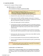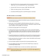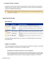
220-0000072 rev01
UIM-DS3
DS3 Uplink Interface Module
Installation
1. Unpack and inspect the equipment.
The following components should be included:
1 UIM-DS3
4 #6 Phillips Panhead Internal Locking Screws
2 #6 Phillips Beige Flathead Screws
If there is any visible damage, do not attempt to connect the device. Contact Customer Support at 1-
877-638-2638 (001-603-427-0600 for international customers) or Support@NetToNet.com.
2. Verify switch configuration.
Ensure that the DIP switches on the UIM-DS3 circuit board are positioned correctly (according to
desired configurations) prior to installing the UIM-DS3 on a Multiplexer Uplink Module or in a Mini
DSLAM. There are two DIP switches located on the top side of the circuit board, opposite the
faceplate. Switches are numbered from left to right; Switch #1 (on the left) is not used, Switch #2
(on the right) is configured as follows:
Transmit Line Buildout
Switch Configuration
Installation Instructions
CAUTION
Net to Net Technologies strongly recommends the use of proper electrostatic discharge (ESD) precautions when
handling this equipment.
Switch #1 Switch #2 Tx Line Buildout
not used
down
0-255 ft.
not used
up
255-450 ft.


