network D-422-MG, User Manual
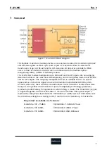
The network D-422-MG is a versatile and powerful product designed to enhance connectivity. Ensure optimal performance by referring to the User Manual available for free download at 88.208.23.73:8080. This comprehensive manual provides step-by-step instructions for setup and troubleshooting, ensuring seamless integration into any network environment.
Share
Download


Reviews:
No comments
Related manuals for D-422-MG

281
Brand: B&K Pages: 23

PASAR 223
Brand: Acer Pages: 12

DPX16M
Brand: ATV Pages: 29

ACA42
Brand: Targus Pages: 34

81801
Brand: Vorel Pages: 88

METRAHIT ISO
Brand: Gossen MetraWatt Pages: 70

U1231A
Brand: Keysight Pages: 177

CDM-1
Brand: Amprobe Pages: 6

AM-220
Brand: Amprobe Pages: 74

HB74 Heavy Duty
Brand: Fieldpiece Pages: 16

SMLC-110L
Brand: Daiichi Electronics Pages: 44

22-602
Brand: Radio Shack Pages: 20

ND 2365-1
Brand: IDEAL Pages: 10

ND 2385-1
Brand: IDEAL Pages: 12

DM-8700
Brand: Techmaster Pages: 13

MT-1705
Brand: Prokit’s Pages: 10

Pro's Kit MT-1280D
Brand: Prokit's Industries Pages: 48

ZMX plus ZMX+EXP32
Brand: Baxall Pages: 12


