background image


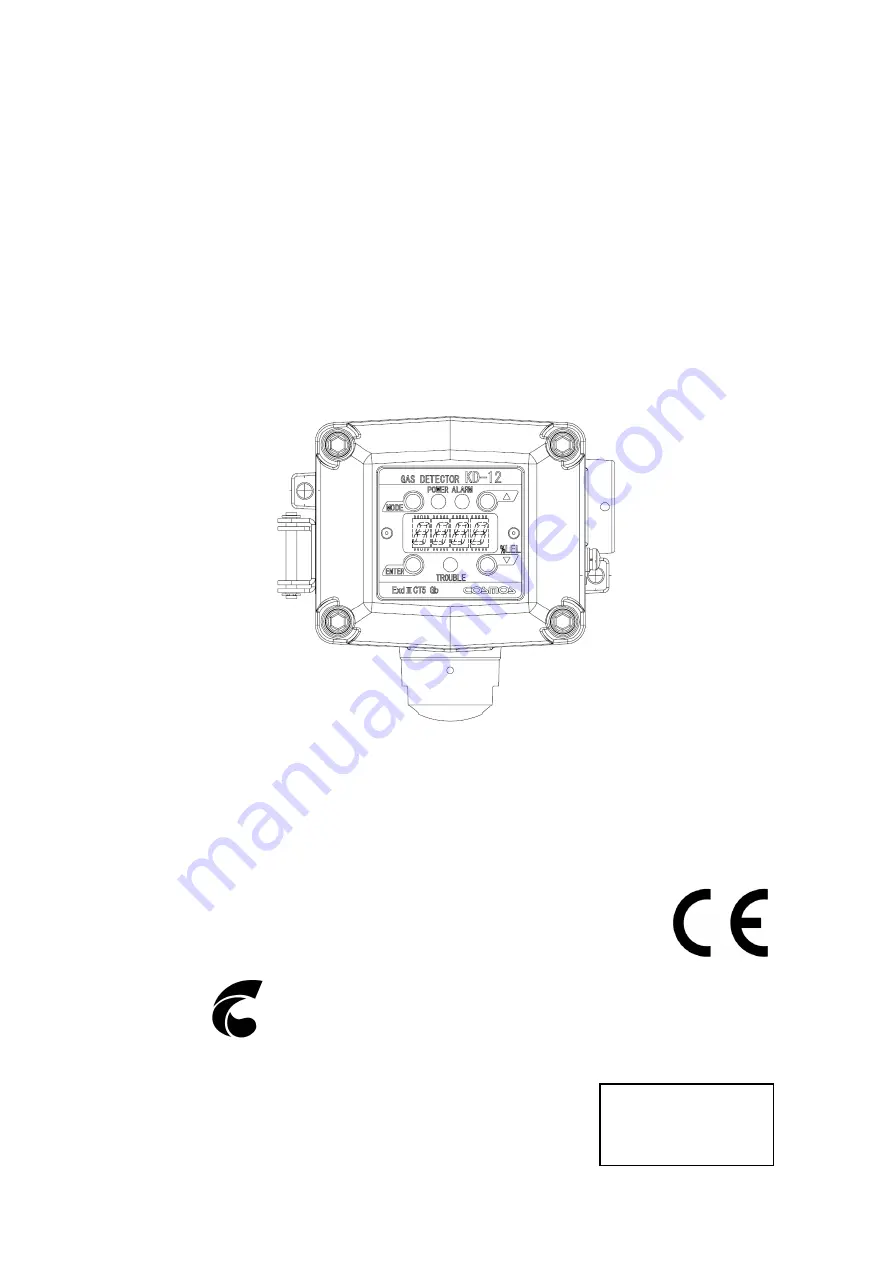
Diffusion type Gas Detector   


Model KD-12B 

(SIL2 Capable) 


Instruction Manual 


 Keep this instruction manual where it is readily accessible. 

 Thoroughly read this instruction manual before using the equipment so it can be used 

safely and correctly. 

 This manual provides information concerning standard specifications. If the specifications 

of your model are nonstandard, refer to the delivery specifications.


Instruction Manual No.

GAE-054-00 

July 2014


New Cosmos Electric Co., Ltd. 

Summary of Contents for KD-12B

Page 1: ... Thoroughly read this instruction manual before using the equipment so it can be used safely and correctly This manual provides information concerning standard specifications If the specifications of your model are nonstandard refer to the delivery specifications Instruction Manual No GAE 054 00 July 2014 New Cosmos Electric Co Ltd ...

Page 2: ...es 31 and 32 Wiring and Connecting Methods See pages 14 to 16 Ground terminals 24 V power supply Indicator E g External alarm Shield Display and Operation in Each Mode See page 19 Maintenance Check and Operation Methods See pages 22 to 30 Troubleshooting See page 33 ...

Page 3: ...ions before Use 17 In Case of Gas Leakage 17 8 Display at Start up Initial Delay 18 9 Display and Operation in Each Mode 19 10 Trouble Alarm 20 11 Maintenance Check and Operation Method 22 11 1 Daily Inspection and Periodical Inspection 22 11 2 Preparing Calibration Gas 23 11 3 Calibration Method 25 Maintenance Mode 25 Zero Adjustment 26 Span Rough Adjustment 28 Full scale and Alarm Set Value Disp...

Page 4: ...intenance and inspection are indispensable to the reliable performance of the Gas Detection Alarm System Be sure to perform the maintenance checks described in this manual Unless the inspection maintenance calibration and proof test are done on the gas detector every six months or once every year the gas detector are not suitable for use in SIL2 safety related applications In order to ensure the c...

Page 5: ...y the construction or electric circuits of the product Otherwise the explosion proof construction of the product may be adversely affected Do not install the product in places or near places where silicone sealant or gas is used Otherwise the performance of the product may be adversely affected Be sure to provide a protective cover optional if the product is installed outdoors Use the product in a...

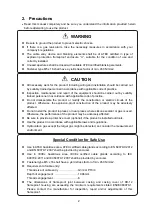
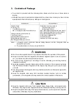
Page 6: ...are for use only by the KD 12 WARNING Do not use the magnetic stick for any purposes other than the operation of this product Keep in mind that when the magnetic stick attracts magnetic objects tools iron pieces etc your hands may become pinched and injured Do not touch the magnet if you are allergic to metal otherwise your skin may become chapped or reddened Generally speaking magnets break easil...

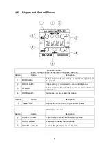
Page 7: ... concentration and set values 9 Cable entry PF3 4orG3 4 pitch 1 81mm Insertion length 10 86mm No of insertion threads 6 Certified cable glands 1 must be provided by end user and used 10 Hexagon socket head cap screw Used for securing the casing cover Use a hexagon wrench with a nominal diameter of 4 mm 11 Hexagon socket set screw Used for securing the cable glands or sensor units Use a hexagon wre...

Page 8: ...ol of the product 3 UP switch Makes adjustments and settings or increases set values and other values 4 DOWN switch Decreases set values and other values Number Name Description 5 Display block Displays the concentration of gas and set values State display indicator Number Name Description 6 POWER indicator A green lamp to display the power supply state 7 ALARM indicator A red lamp to display the ...

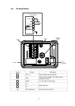
Page 9: ...scription 1 24 V Power supply voltage positive 2 GND Power supply voltage and analog signal negative common 3 Signal 4 to 20 mA analog signal 4 ZA External contact 5 ZC Ground terminal Used to ground the frame Terminal block Ground terminal Lever Sensor connector O ring Clamp 4 to 20 mA 24 V ...

Page 10: ...EX certified blanking elements Fastener type M5 x 16 shall have a yield stress factor of min 450 N mm2 The dimensions of flameproof joint between casing and casing cover of KD 12 flameproof housing are exceeding the minimum requirements stated EN IEC60079 1 Please contact the manufacturer for inspection repair and or adjustments of this flameproof Installation of cable gland and sensor Casing to c...

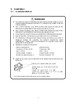
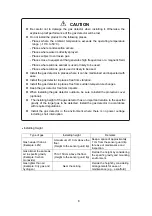
Page 11: ...es where the ambient temperature exceeds the operating temperature range 10 C to 50 C Places where condensation occurs Places where water is directly sprayed Places subject to corrosive gas Places close to equipment that generates high frequencies or a magnetic field Places where silicone sealant is used or likely to be used Places where silicone gas is used or likely to be used Install the gas de...

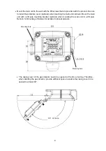
Page 12: ... unit with a 2B pole mounting bracket optional when mounting the main unit to a 2B pole Refer to 5 3 Mounting of Options for details of optional products The casing cover of the gas detector needs be opened at the time of wiring Therefore when installing the gas detector provide sufficient space to enable the casing cover to be opened to at least 90 Mounting hole Mounting hole 90 or more ...

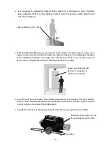
Page 13: ...t a height more than 3m from the floor we recommend you to use a suction type gas detector with a sampling tube up to the ceiling A sensor guard is not necessary when installing the detector on the ceiling or a higher location However when installing the detector on a lower place like the floor a sensor guard is required in order to protect the sensor from water splash Consider the direction of th...

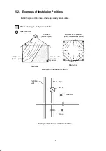
Page 14: ...ample of Installation Position Partition wall Pipe Valve Detector Flange Example of Outdoor Installation Position Entrance Suction port Roof fan Exhaust port Entrances and windows Suction and exhaust ports Gas detector mounting position Places where gas easily accumulates Gas detector Side view Plan view ...

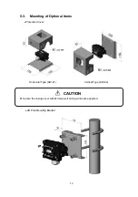
Page 15: ...12 5 3 Mounting of Optional items Protective Cover Horizontal Type KW 41 Vertical Type KW 42 2B Pole Mounting Bracket CAUTION Secure the casing cover with M3 screws if strong winds are expected ...

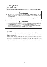
Page 16: ...on which requires a three conductor cable without the external contact function make sure that the maximum diameter of the cable conductor is 2 00 mm2 CAUTION All necessary work for the product including wiring and installation should be carried out by suitably trained personnel in accordance with applicable code of practice Inspection maintenance and repair of the equipment should be carried out ...

Page 17: ...kness of 1 25 to 2 00 mm2 Make sure that the power supplied to the product is within the specified voltage range Make sure that the load resistance of the signal line including the resistance of the wire is 300 ohm or less WARNING Before opening the casing cover of the gas detector be sure to turn off the product and all devices e g indicator unit and signal converter connected to the product If t...

Page 18: ...Connection Example with Power Supply Side Grounded System Configuration Example For details refer to the Instruction Manual of each device KD 12B SIL PLC Valves 4 20 mA Gas Controller Sensor Subsystem Logic Subsystem Actuator Subsystem 指示計 ユニット 電源 2 Ground terminals CVVS cable 24V power supply Indicator Shield External alarm Ground terminal on power supply side Not grounded Grounded ...

Page 19: ...e GND terminal 7 The lead wire will be automatically secured when the screwdriver is lifted 8 Check that the power supply cords are securely connected to the terminals This completes the power supply preparations 9 Wire the analog signal and external contact terminals if required 10 Tighten the hexagon socket bolts tightening torque 0 8 2 4 N m on the four corners of the main unit and close the ca...

Page 20: ...table gas detector and confirm the safety before entering the detection site DANGER Without panicking check that there is no fire around the product Do not touch any electric switches under any conditions Sparks from turning electric switches ON or OFF may cause ignition CAUTION Before turning ON any of the devices e g indicator unit signal converter connected to the product recheck that all of th...

Page 21: ...ashed for approximately 25 seconds 4 When the POWER indicator green lamp is lit the start up of the main unit is completed and the main unit will be in gas monitor mode MEMO If the sensor unit has not been turned ON for a long time after the product is shipped from factory it may take some time for the sensor output to stabilize If needed turn ON the product for approximately one week and make the...

Page 22: ...tration Displayed alternately Test value Displayed alternately Analog signal 4 to 20 mA Fixed at 1 6 mA Gas concentration value is output Test value is output Value corresponding to the gas concentration or fixed value 1 6 mA is output according to user choice Test value or fixed value 1 6 mA is output according to user choice Contact operation Does not operate OFF SHORT Operates ON OPEN Operates ...

Page 23: ...ensor connector failure or broken wire has possibly occurred contact your local representative Lamp is OFF Zero point adjustment error There is gas in the ambient air After checking the ambient air make the zero adjustment again Lamp is OFF Span adjustment error The gas concentration applied for adjustment is wrong After checking the type and concentration of gas make a span adjustment again If th...

Page 24: ...mains in maintenance mode Turn off the gas detector Wait a few seconds then turn back on If a screen other than the above is displayed refer to the 12 Troubleshooting section If the product does not reset to normal operation after taking the measures shown in the table or if the problem is not listed in the table contact your local representative If the product goes into any unintended mode during...

Page 25: ...nspection gas to the gas detector and check the operation of the alarm Use the calibration cap apply inspection gas and check the operation of the alarm Condition around gas detector Check that nothing interrupts the diffusion of gas around the gas detector Periodical inspection At least once per year Consult your local representative Use optional products to make actual gas inspections Periodical...

Page 26: ... Gas Calibration gas is used for actual gas inspection The following example shows how to prepare 0 72 vol 40 LEL isobutane as a reference gas With a standard gas cylinder Standard gas cylinder Gasbag 0 72 vol isobutane air balance ...

Page 27: ...aw gas Draw a little more than you actually need then discharge the excess 3 Transferring raw gas into a quantitative pump Connect a syringe to the inlet of a quantitative pump then pull out the pump s piston Raw gas in the syringe is sucked into the pump Remove the syringe and pull the piston all the way out 100ml 4 Making diluted gas Connect an empty gasbag to the outlet of the quantitative pump...

Page 28: ...e mode 6 Upon completion of this mode the product will automatically return to gas monitor mode 7 While is displayed the maintenance mode is being executed 8 This mode will be canceled by repeating the same operation 1 to 6 above turning the product OFF or waiting for 8 hours Carefully handle and make settings with the magnetic stick because the magnet is very powerful For details refer to 3 Conte...

Page 29: ...followed by The product is ready to work but nothing has been operated 3 Press the UP or DOWN switch of the main unit with the magnetic stick and adjust the value to 4 Press the ENTER switch of the main unit 5 6 When the above items are displayed the zero adjustment is completed 7 Upon completion of the zero adjustment the product will automatically return to gas monitor mode If an error is displa...

Page 30: ...switch of the main unit with the magnetic stick and adjust the display of the main unit to the actual span gas concentration 9 Press the ENTER switch 10 The span fine tuning is completed when is displayed 11 Upon completion of the span fine tuning the product will automatically return to gas monitor mode 12 Remove the gasbag Perform span rough adjustment if or is displayed If an error is displayed...

Page 31: ...djust the display of the main unit close to the actual span gas concentration 9 Press the ENTER switch 10 The span rough adjustment is completed when is displayed 11 On completion of the span rough adjustment the product will automatically return to gas monitor mode 12 Remove the gasbag MEMO Precise adjustment is not performed only by span rough adjustment Perform span fine tuning after span rough...

Page 32: ...mple After zero adjustment will be displayed 3 Press the UP or DOWN switch of the main unit with the magnetic stick and adjust the value to 4 Press the ENTER switch of the main unit Full scale Alarm set value 5 When the above items are displayed in sequence and repeatedly the user can check the full scale and alarm set values 6 After the full scale and alarm set values are displayed the product wi...

Page 33: ...f the full scale of the product is 2000 ppm The test operation of the product is possible in a concentration range from 10 LEL to 110 LEL if the full scale of the product is 100 LEL 6 Press the UP or DOWN switch of the main unit and set the desired calibration concentration Then the test will start If the setting is outside the operating range or will be displayed 7 To quit the test mode press the...

Page 34: ...s of the sensor connector When closing the casing cover make sure that the power supply cord harness or O ring is not caught by the casing cover WARNING Be sure to turn OFF the indicator unit signal converter or main body equipment before replacing a sensor unit Otherwise they may become a source of ignition Be sure that the sensor and the sensor connector have been firmly connected to the detecto...

Page 35: ...e sensor guard 10 Tighten the bolt with a hexagon socket tightening torque 0 8 2 4 N m on each of the four corners of the main unit with the provided hexagon wrench with a nominal diameter of 4 mm and close the casing cover of the main unit 11 Turn ON the power supply connected to the product 12 When the sensor unit has been replaced it is necessary to make zero adjustment and span adjustment afte...

Page 36: ...r wires are broken contact your local representative The detected gas concentration and are flashing alternately The product is in maintenance mode Return the product to gas monitor mode P 25 Maintenance Mode There is no alarm contact output The product is in maintenance mode Return the product to gas monitor mode P 25 Maintenance mode Incorrect wiring connection Check and reconnect the wiring P 1...

Page 37: ... period Make sure that the load resistance of the analog signal is less than 300 ohm including the wiring resistance Gas alarm contact one stage only 1a no voltage contact output Non latching Rated load 0 5 A at 250 VAC or 0 5 A at 30 VDC resistance load Explosion proof Class Ex d IIC T5 Japan II 2 G Ex d IIC T5 Gb Europe Ex d IIC T5 Gb IECEx Approval EC type examination certificate DEMKO 08 ATEX ...

Page 38: ...ing protruding parts Weight Approx 1 2 kg Mounting method Wall mounting The above specifications are subject to change without notice If your specifications are nonstandard refer to the delivery specifications 14 Markings of explosion proof Nameplate detail Serial number label detail Rated label detail Certificate label detail Warning label detail List of hazardous locations standard EN 60079 0 20...

Page 39: ...arranty periods If after examination of an allegedly defective product returned to New Cosmos with freight prepaid should it be found that the product fails to conform to this warranty the Customer s only remedy and New Cosmos s only obligation shall be at New Cosmos s sole discretion replacement or repair of the non conforming product or refund of the original purchase price of the non conforming...

Page 40: ...eriod of designed life expectancy The product may become unusable before the next calibration is performed The life of the catalytic combustion type sensor incorporated in the KD 12B is approximately three years after the date of purchase The sensor may not detect gas correctly with the lapse of approximately three years Replace the sensor at intervals of approximately three years The life of the ...

Page 41: ...ition of explosive gases outside of it Preset alarm value A preset value for the alarm to go off when gas concentration reaches a certain value Gas to be detected Gas that is detected and indicated which sets off an alarm Detection range Range of gas s concentration that can be indicated and set off an alarm Alarm accuracy Difference between the preset alarm value and gas concentration when an ala...

Page 42: ...e electric equipment that has no potential to create a hazardous atmosphere Hazardous atmosphere Atmosphere within the explosive limit where explosive gas and air are mixed LEL Lower Explosive Limit The lowest concentration of flammable gas that will explode when mixed with air and ignited Quoted from gas detection terms and detector tube gas meter terms used by the Industrial Gas Detector Alarm A...

Page 43: ...40 ...

Page 44: ...ction Manual are available Contact the following address for ordering information Distributor Manufacturer New Cosmos Electric Co Ltd 2 5 4 Mitsuya naka Yodogawa ku Osaka 532 0036 Japan Phone 81 6 6309 1505 Fax 81 6 6308 0371 Email e info new cosmos co jp http www new cosmos co jp New Cosmos Electric Co Ltd ...

Reviews: