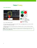
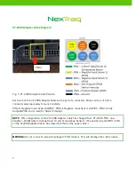
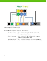
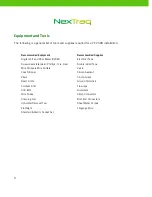
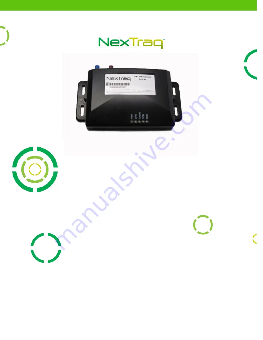
background image


NexTraq VT-2300 Installation Guide 


Version 1.1 


Summary of Contents for VT-2300

Page 1: ...NexTraq VT 2300 Installation Guide Version 1 1 ...

Page 2: ...tten permission of NexTraq This installation guide does not constitute a warranty as to any product or service except to the extent expressly provided in the agreement under which such a product or service was provided Trademarks NexTraq is trademarked All other trademarks and service marks contained within this document are the property of their respective owners Disclaimer The complete terms and...

Page 3: ...Glass Mount 11 Dashboard Mount 11 Covert Installation 12 Vehicle Wiring 13 Ground 13 Power 13 Ignition 14 VT 2300 Location 15 Mounting Location 16 Post Installation Testing 17 Installation Troubleshooting 18 Appendix A Technical Specifications 20 Appendix B Garmin Device Installation Notes 22 Appendix C 1 Wire Device Installation Notes 24 Appendix D Starter Interrupt Installation Notes 29 ...

Page 4: ...he following Equipment and Tools Types of Antenna Mounts Placement of VT 2300 Installations Troubleshooting Appendices covering installation of available peripheral devices VT 2300 Hardware The VT 2300 consists of a nylon plastic engineered housing containing the electronic components Additional equipment includes a separate power connection cable and a modular cellular GPS antenna Specifications ...

Page 5: ... chance of an installer incorrectly wiring the unit Five connectors make up the VT 2300 s configuration power GPIO a serial port interface GSM antenna connector and GPS antenna connector VT 2300 Wiring Diagrams Fig 2 Schematic of VT 2300 Pin Out Power Cable Pin Signal Color 1 Ground Black 2 Positive Input Sensor 1 GPIO1 Green 3 Ignition White 4 12V Supply Red Pin Out IO VT 2300 Adapter Cable Pin S...

Page 6: ...quires ONE positive input sensor GPIO1 in addition to normal 3 wire install PIN2 green wire will be covered by heat shrink Installer will need to cut back heat shrink to expose for sensor install NOTE While the power cable is backwards compatible with the VT 2200 PIN2 green wire is not functional on VT 2200 devices ...

Page 7: ...PIO2 PIN3 is Negative Input Sensor 2 GPIO3 PIN4 is Sink Output GPIO4 and is used for Starter Interrupt NOTE PIN configuration of the VT 2300 Adapter Cable has changed from VT 2200 PIN1 now handles 1 Wire data including Driver ID and Temperature Sensors The positive input GPIO1 PIN1 on the VT2200 Adapter Cable has moved to PIN2 on the power cable WARNING Do not connect a wire with voltage to PIN1 G...

Page 8: ...hree connectors Two PIN connector Used with Driver ID Key Fob Reader or Temperature Sensing Probe Black Green Four PIN connector Used with Driver ID Key Fob Buzzer LED or any other output Yellow Blue Orange White Three PIN connector Used with two inputs and one output Blue White Black ...

Page 9: ... Electrical Tape Screwdrivers standard Phillips Torx Hex Double sided Tape Wire Strippers Wire Cutters Velcro Coax Stripper Silicon Sealant Pliers 5 Amp Fuses Razor Knife Ground Terminals Cordless Drill Tie wraps Drill Bits Grommets Wire Snake Crimp Connectors Crimping tool Butt End Connectors Upholster Removal Tool Sheet Metal Screws Flashlight 18 gauge Wire Standard Metric Socket Set ...

Page 10: ...standard antenna type used for the VT 2300 is a combination antenna in the style of either a blade or a puck Two FAKRA connectors provide connection for GPS blue and GSM violet Fig 7 Combo Blade Antenna The combination antenna combines the cellular and GPS antennas into a single antenna package The combination antenna can be mounted on glass on the dashboard or as a covert installation ...

Page 11: ...40 percent of the sky The antenna needs to be mounted as horizontal as possible The antenna should not be mounted behind windscreens ladder racks or other radio transmission antennas Fig 8 Glass Mount Dashboard Mount The antenna should be mounted on the dashboard with a view of at least 40 percent of the sky It is recommended that the antenna be as horizontal as possible When mounting the blade an...

Page 12: ...a at the top center of the windshield behind the rear view mirror or at the top right corner of the windshield See Glass Mount notes Covert Installation When mounting a covert installation make sure that the antenna is not shielded by metal However it can be mounted on non metallic materials such as plastic fiberboard fiberglass etc When mounting the blade antenna it should be oriented with the to...

Page 13: ... or plate Temporarily connect VT 2300 to ensure it is on constant power before your final placement Power Find constant 12 volt wire and slide crimp over wire Slide red fused wire from NexTraq power cable all the way into the holder and crimp with pliers Cable tie the fused wire to the lead wire Next find an ignition wire that is 12 volt when ignition is in the ON position and open or ground when ...

Page 14: ...re Ignition wires maintain a voltage through the crank The best place to pull power is at the ignition harness leading to the ignition switch See Appendix A for specifications relating to power ground ignition and sensors IMPORTANT Late Model Vehicle Installation When installing a VT 2300 in any late model vehicle verify all connections using a digital multimeter In some instances obtaining power ...

Page 15: ...e safely secured to a firewall or zip tied onto a permanent fixture VT 2300 can be secured underneath the dashboard on ether the driver or passenger side in any location that will not interfere with the safety of vehicle operation The device can be secured by the individual tie wraps or by self taping screws or Velcro tape Fig 11 VT 2300 Location Avoid placing VT 2300 near moving parts or next to ...

Page 16: ...he running of any antenna wires or power cable Fig 13 VT 2300 Mounting Mounting Location The mounting of the VT 2300 is limited by the 3 foot length of power cable The unit must be placed within the vicinity of the power connections Locate a flat metal or plastic surface big enough to fit the unit and use at least two screws to mount Tie wrapping VT 2300 to a wiring harness is also acceptable ...

Page 17: ...uld be a solid blue light on PWR GPS and COM NOTE The Radio LED will flicker while receiving or transmitting messages When ignition is off only the power light will be on The unit will be in standby mode When the unit has been installed and operation had been verified place black tape across the surface of the LEDs to conceal the lights Verify with the Customer Service Representative that the VT 2...

Page 18: ...antenna s view of the sky Check the antenna cable for pinching or crimping in the corner Reset power COM light not on or blinks Check GSM antenna connections Ensure that nothing obstructs the antenna such as metallic sunscreens Make sure VT 2300 is within the AT T coverage map http www wireless att com coverageviewer type data Contact NexTraq Customer Service for assistance Reset power Ignition li...

Page 19: ...s turned on or off Check power on mobile Be sure to view the correct mobile in the NexTraq Web application Check antenna connections and placement Drive the vehicle for more than two miles at 30 mph See Appendix A for Technical Specifications See Appendix B for Garmin Device Installation Notes See Appendix C for 1 Wire Device Automatic Driver ID and Temperature Sensor Installation Notes See Append...

Page 20: ... Automotive Grade FAKRA connectors Electrical The VT 2300 power cable is a 4 pin connector for simple installation The power cable is preconfigured for battery ground and ignition Power Operating Range 8v 24v DC Consumption Normal 55 60mA Idle 1 7 32 mA Hibernate 1mA Data Communication Interfaces The VT 2300 can interface with external devices for enhanced tracking and navigation These options inc...

Page 21: ... Acquisition Time 3 s Hot Start 30 s Warm Start 35 s Cold Start Position Accuracy 2 5m CEP Accessories The VT 2300 has cabling available for standard installation needs The possible accessories include Driver ID with 1 Wire protocol Temperature Sensors with 1 Wire protocol Starter Interrupt 2m 6 5ft GPS GPRS combo blade or puck style antenna with automotive grade FAKRA connectors 3 wire power adap...

Page 22: ...mpatible models is available at http www8 garmin com solutions pnd supportedproducts jsp As an alternate to the DW 00 G0011 FMI cable the DW 00 G0014 FMI cable is required to support Garmin s traffic reporting feature Use the same ignition wire for the Garmin PND power source as you have for the mobile device power source It is necessary to have a power source with sufficient power capability to s...

Page 23: ...in PND is operational and communicating with the application Call NexTraq Customer Service at 800 358 6178 for post installation verification Customer Service Hours Monday Friday 7 00am to 11 00pm Eastern Time Saturday Sunday 7 00am to 3 00pm Eastern Time ...

Page 24: ...ader DW 00 M0040 Key Fob Buzzer DW 00 M0042 From the VT 2300 Adapter Cable the Key Fob Reader uses the connector with green PIN1 and black PIN6 wires Key Fob Buzzer uses the connector with blue and white PIN5 and black PIN6 wires The Key Fob Reader should be placed in an easily accessible area for the driver The key fob buzzer can be placed at the installer s discretion After installation when the...

Page 25: ...d with the iButton s ID number has turned on the vehicle s ignition NOTE A customer may order an LED light instead of the Key Fob Buzzer The light is wired in the same manner as the buzzer Placement should be in clear line of vision for the driver Automatic Driver ID Wiring Diagram ...

Page 26: ...ing Probe connects to the VT 2300 6 pin Adapter Cable using the 2 pin connector with green PIN1 and black PIN6 Additional cable may be added for effective placement of the probe However the total length of the cable should not exceed 50 feet For cable length greater than 15 feet use CAT 5 type cable When considering placement of the sensor remember the sensor is not waterproof and should not get w...

Page 27: ...nect the red and black Extension Adapter Cable to the green PIN1 and black PIN6 wires from the 6 pin Adapter Cable Then splice the raw end of the Extension Adapter Cable to the Temperature Sensing Probe and the iButton Reader as follows a Splice the blue Temperature Sensor red iButton Reader and red Extension Adapter Cable wires together using electrical splice connectors such as Scotch locks b Sp...

Page 28: ...c Driver ID plus Temperature Sensor Verify with NexTraq Customer Service that the Automatic Driver ID and Temperature Sensor are operational and displaying information in the web application Call NexTraq Customer Service at 800 358 6178 for post installation verification ...

Page 29: ...the Starter Interrupt Relay Follow the wiring diagram below to connect the Starter Interrupt Relay red relay wire to the ignition switch wire and the white relay wire to the starter wire Important Relay wiring is designed to enable the relay only when energized by the ignition switch engaging the starter Off State Starter Interrupt Not Active default state The relay setup receives its power from t...

Page 30: ...s starter another command must be issued from the Web Application to release control of the Starter Interrupt relay making it inactive again Caution During the interrupt of the starter a considerable amount of current is grounded through the relay connections The relay is rated for automotive applications and when properly installed the relay is powered only when the ignition switch is engaged If ...

Page 31: ...31 Starter Interrupt Wiring Diagram ...

Page 32: ...vice the relay will emit an audible click After the signal is received power to the ignition is denied The vehicle will not start on next start attempt The voltmeter registers no power as in this demonstration To allow ignition again another signal must be sent from the application and received by the mobile device Testing of the Starter Interrupt option will be part of the post installation verif...

Reviews: