background image

INSTALLATION INSTRUCTIONS

NI SCXI -1379

Terminal Block for the NI SCXI-1130

This guide describes how to install and connect signals to the 
National Instruments SCXI-1379 terminal block to configure the 
SCXI-1130 as an 8x32, 1-wire matrix.

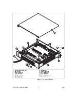
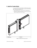
The SCXI-1379 terminal block, which installs in front of the SCXI-1130 
switch module, uses screw terminals to connect signals and the trigger 
input and trigger output signals to the switch. 

Refer to the 

NI Switches Getting Started Guide

 to determine when to install 

the terminal block.

Conventions

The following conventions are used in this guide:

»

The 

»

 symbol leads you through nested menu items and dialog box options 

to a final action. The sequence 

File»Page Setup»Options

 directs you to 

pull down the 

File

 menu, select the 

Page Setup

 item, and select 

Options


from the last dialog box.

This icon denotes a tip, which alerts you to advisory information.

This icon denotes a note, which alerts you to important information.

This icon denotes a caution, which advises you of precautions to take to 
avoid injury, data loss, or a system crash.

bold

Bold text denotes items that you must select or click in the software, such 
as menu items and dialog box options. Bold text also denotes parameter 
names and information on hardware labels.

̭͈Ρ΅νιϋΠ͉ͅȂ඾ུࢊβȜΐ͜܄̞̳ͦ̀͘͘ȃ

Summary of Contents for SCXI-1379

Page 1: ... following conventions are used in this guide The symbol leads you through nested menu items and dialog box options to a final action The sequence File Page Setup Options directs you to pull down the File menu select the Page Setup item and select Options from the last dialog box This icon denotes a tip which alerts you to advisory information This icon denotes a note which alerts you to important...

Page 2: ...damage when you handle the terminal block take the following precautions Caution Never touch the exposed pins of connectors Ground yourself using a grounding strap or by touching a grounded object Touch the antistatic package to a metal part of the chassis before you remove the terminal block from the package Remove the terminal block from the package and inspect the terminal block for loose compo...

Page 3: ... the top cover screw 3 Unsnap and remove the top cover 4 Loosen the two strain relief screws on the strain relief assembly 5 Run the signal wires through the strain relief opening 6 Insert the stripped end of the wire fully into the terminal Secure the wire by tightening the screw of the terminal No bare wire should extend past the screw terminal Exposed wire increases the risk of a short circuit ...

Page 4: ... 1 Terminal Block Top Cover 2 Signal Wires 3 Safety Ground Lug 4 Screw Terminals 5 Column Connector 6 Rear Connectors 7 Top Cover Screw 8 Thumbscrew 9 Column Connector 10 Strain Relief Screw 11 Strain Relief Bar 12 Strain Relief Opening 13 Row Connector 1 7 5 4 3 12 11 10 9 8 6 13 2 ...

Page 5: ... EXPANSION CONNECTOR 176 POSITION CONNECTOR 176 POSITION CONNECTOR 128 POSITION ROW EXPANSION CONNECTOR COLUMN 0 C0 1 C1 2 C2 3 C3 4 C4 5 C5 6 C6 7 C7 8 C8 9 C9 10 C10 11 C11 12 C12 13 C13 14 C14 15 C15 32 C16 33 C17 34 C18 35 C19 36 C20 37 C21 38 C22 39 C23 40 C24 41 C25 42 C26 43 C27 44 C28 45 C29 46 C30 47 C31 1 Wire 0 R0 1 Wire ROW 1 R1 2 R2 3 R3 4 R4 5 R5 6 R6 7 R7 COLUMN EXPANSION CONNECTOR ...

Page 6: ... 2 c8 COLUMN 8 c21 COLUMN 37 r3 ROW 3 c9 COLUMN 9 c22 COLUMN 38 r4 ROW 4 c10 COLUMN 10 c23 COLUMN 39 r5 ROW 5 c11 COLUMN 11 c24 COLUMN 40 r6 ROW 6 c12 COLUMN 12 c25 COLUMN 41 r7 ROW 7 c13 COLUMN 13 c26 COLUMN 42 c0 COLUMN 0 c14 COLUMN 14 c27 COLUMN 43 c1 COLUMN 1 c15 COLUMN 15 c28 COLUMN 44 c2 COLUMN 2 c16 COLUMN 32 c29 COLUMN 45 c3 COLUMN 3 c17 COLUMN 33 c30 COLUMN 46 c4 COLUMN 4 c18 COLUMN 34 c3...

Page 7: ...d the rows of a 4x32 matrix using a matrix expansion plug The matrix expansion plug connects columns to expand the rows To expand the rows of a matrix complete the following steps 1 Connect two SCXI 1379 terminal blocks to the front connectors of the two adjacent SCXI 1130 modules 2 Tighten the top and bottom chassis screws on the back of the terminal block rear panels to hold them securely in pla...

Page 8: ...terminals in one of the SCXI 1379 terminal blocks 2 Connect the other end of the matrix expansion cable to one of the ROW CONNECTION CABLE TERMINALS in another SCXI 1379 3 Connect the two SCXI 1379 terminal blocks to the front connectors of the two SCXI 1130 modules 4 Tighten the top and bottom chassis screws on the back of the terminal block rear panels to hold them securely in place Figure 4 Col...

Page 9: ...e 5 and complete the following steps the SCXI 1130 should already be installed in an SCXI chassis 1 Plug the SCXI 1379 onto the front connectors of the SCXI 1130 2 Tighten the top and bottom thumbscrews on the back of the terminal block rear panel to hold it securely in place Figure 5 Installing the SCXI 1379 Terminal Block 1 Thumbscrew 2 Front Connectors 3 SCXI 1130 4 SCXI 1379 4 1 3 2 ...

Page 10: ...ility Emissions EN 55011 Class A at 10 m FCC Part 15A above 1 GHz Immunity EN 61326 1997 A2 2001 Table 1 EMC EMI CE C Tick and FCC Part 15 Class A Compliant Note For EMC compliance you must operate this device with shielded cabling CE Compliance This product meets the essential requirements of applicable European Directives as amended for CE marking as follows Low Voltage Directive safety 73 23 EE...

Page 11: ...nal Instruments trademarks Other product and company names mentioned herein are trademarks or trade names of their respective companies For patents covering National Instruments products refer to the appropriate location Help Patents in your software the patents txt file on your CD or ni com patents 2003 2007 National Instruments Corporation All rights reserved 373691B Nov07 ...

Reviews: