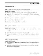
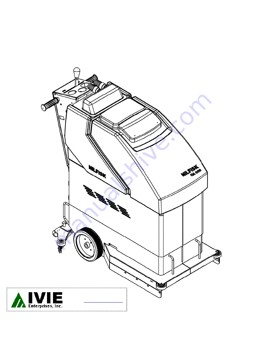
background image

Model 66324400

12/94    Form Number 043023

NILFISK BA 500

Service Manual

ORDER PARTS  

Online: 

www.ivie-ent.com

Phone: (918)254-5161 

Summary of Contents for BA 500

Page 1: ...Model 66324400 12 94 Form Number 043023 NILFISK BA 500 Service Manual ORDER PARTS Online www ivie ent com Phone 918 254 5161 ...

Page 2: ...nt 8 Brush Drive System Maintenance 7 Brush Drive System Troubleshooting 10 Differential Replacement 16 Potentiometer Adjustment 20 Safety 1 Solenoid Valve Removal Disassembly Cleaning 4 Solution System Maintenance 4 Solution System Troubleshooting 6 Specifications Maintenance 2 Squeegee Adjustment 13 Vacuum Motor Removal 12 Vacuum System Maintenance 11 Vacuum System Troubleshooting 14 Wheel Drive...

Page 3: ...njury or damage to the machine or other property ________________________________________________________________________________________________________________________________________________________________________________________________________________________________________________________________________ GENERAL SAFETY INSTRUCTIONS WARNING Keep sparks flame and smoking materials away from ...

Page 4: ... cm Machine Height 43 5 inches 110 cm Drive Wheel 8 inch 20 cm soft ride wheels Solution Tank Capacity 12 gal 45i Recovery Tank Capacity 12 gal 45i Coverage Rate 7 500 sq ft 697 m2 per hour Machine Weight 266 lbs 121 kg net w o batteries 558 lbs 253 kg w four 244 AH batteries 376 lbs 175 kg w two 93 AH batteries 350 lbs 159 kg shipping weight General Specifications Brush Motor 24 volt 1 2 hp dc mo...

Page 5: ...________________________________________________________ MAINTENANCE CHART Once a Once a Once a MAINTENANCE ITEM Daily Week Month Year Clean and inspect the tanks and hoses X Clean the brushes and pads X Clean the squeegee X Charge the batteries X Check battery water level X Lubrication X Vacuum motor carbon brushes X MAINTENANCE 3 BA 500 Service Manual ORDER PARTS Online www ivie ent com Phone 91...

Page 6: ...This automatically flushes loose dirt from solution filter 2 Put clean warm water into the solution tank and let it drain through the drain hose 3 Put the plug in the drain hose and put about 2 inches of clean water in the solution tank 4 Put the machine controls in the following positions Key Switch ON Solution Switch on left side of handle ON Brush drive lowered Twist Grips Forward Flow control ...

Page 7: ...___________________________________________ SOLENOID VALVE DISASSEMBLY AND CLEANING 1 Remove the solenoid valve See the Solenoid Valve Removal section for instructions 2 See Figure 2 Remove the 2 D screws and nuts and disassemble the valve be careful not to lose any internal parts 3 Thoroughly wash dirt from block E and diaphram F 4 After reassembling test the solenoid valve for proper operation D...

Page 8: ...d Solution Filter Drain solution tank using the clear plastic drain hose on back of machine This automatically flushes loose dirt from solution filter If solution still does not flow remove and disassemble the tee fitting under the solution tank remove and clean the filter thoroughly 3 Clogged Solenoid Valve Remove disassemble and clean the solenoid valve See the Solenoid Valve Disassembly and Cle...

Page 9: ...________________________________________________________________________________________________________________________________________________________________________________________ BELT ADJUSTMENT OR REPLACEMENT 1 Drain the solution and recovery tanks 2 See Figure 1 Tip the machine back as shown and place a jack stand under the front end 3 See Figure 2 Turn nut A counterclockwise to loosen the...

Page 10: ...h 9 66 mm or shorter replace both carbon brushes Remove all loose carbon and dirt from the inside of the motor 5 Follow steps 1 3 in reverse order to reassemble 6 Test the motor to make sure it operates properly ____________________________________________________________________________________________________________________________________________________________________________________________...

Page 11: ...ck stand under the front end FIGURE 5 FIGURE 6 7 Remove screw H the idler assembly and the belt from the machine 8 Remove 2 I bolts and 2 J nuts Set the front of the machine back on the floor and pull the brush drive motor up and out of the machine 9 Remove the pulley from the old motor and install it on the new one 10 Follow steps 1 7 in reverse order to reassemble Tighten nut G until the tension...

Page 12: ...adjust belt tension ________________________________________________________________________________________________________________________________________________________________________________________________________________________________________________________________________ Problem Brush motor will not start when twist grips are turned Possible Cause and Remedy 1 Tripped brush motor circ...

Page 13: ...it around or over so a new edge with a sharp corner faces toward the front of the machine 3 See Figure 1 Disconnect squeegee hose A from left side of recovery tank cover B Park the machine outside or near a floor drain and use a garden hose to back flush dirt down and out of squeegee hose A CAUTION Do not flush hose C unless it is disconnected from the vacuum motor 4 Remove cover B from the recove...

Page 14: ... tank and tip it to the side of the machine 2 Drain the solution tank disconnect the hose from the bottom of the tank and remove the tank from the machine 3 Disconnect one of the battery cables 4 See Figure 2 Remove the 4 G screws and lift cover H off of the machine along with FIGURE 2 bracket I 5 See Figure 3 Remove the 4 J screws 6 Disconnect the vacuum motor wiring connector 7 Disconnect hose K...

Page 15: ..._______________________________________________________________________________________________________________________________________________________________ SQUEEGEE ADJUSTMENT 1 Adjust the large knob M on the back of the squeegee mount until both front and rear blades touch the floor equally Front M 13 BA 500 Service Manual ...

Page 16: ...uum motor ________________________________________________________________________________________________________________________________________________________________________________________________________________________________________________________________________ Problem Water in vacuum motor Possible Cause and Remedy 1 Operator using high sudsing detergent use low sudsing detergent or ...

Page 17: ..._________________________________________________________________________________________________________________________________________________________ TROUBLESHOOTING continued Possible Cause and Remedy 1 Tripped vacuum motor circuit breaker see Figure 5 press reset button check circuit breaker for continuity 2 Defective vacuum switch see Figure 6 remove cover panel from back of control handle ...

Page 18: ...oning bolt A 3 Disconnect the master link in the chain and remove the chain FIGURE 1 4 Remove the B bolts and remove the wheels 5 Remove the 6 C differential mounting bolts and nuts and D bushings Remove the differential from the machine 6 Remove the sprocket E collars F bearings and G bushings from the old differential and install them on the new one take note of the location of the E collars on ...

Page 19: ...ation ________________________________________________________________________________________________________________________________________________________________________________________________________________________________________________________________________ DRIVE CHAIN REPLACEMENT OR ADJUSTMENT ___________________________________________________________________________________________...

Page 20: ...wheel drive forward or reverse Possible Cause Remedy 1 Tripped wheel drive circuit breaker see Figure 2 press reset button if wheel drive still doesn t work check circuit breaker for continuity FIGURE 2 2 Defective wheel drive motor follow instructions below Jack up the rear of the machine to lift the drive wheels off the floor Remove back panel from control handle Remove the plastic cover from th...

Page 21: ...o the full forward position If you do not get these readings follow potentiometer adjustment instructions If you do get these readings go to the next test Connect an ohmmeter to the green and yellow wires The meter should read 2400 2600 ohms in neutral and decrease to 100 300 ohms when the twist grips are turned to the full forward position If you do not get these readings follow potentiometer adj...

Page 22: ...ust the potentiometer 1 Remove the back panel from the control handle 2 See Figure 3 Loosen the 2 set screws in pulley B 3 Remove the plastic cover from the speed control 4 Carefully pull connector A off the speed control pull toward back of machine 5 Connect an ohmmeter on 0 x 100 scale to the green and yellow wires at the connector 6 Turn the potentiometer shaft until the meter reads between 240...

Page 23: ..._______________________________________ BATTERY MAINTENANCE Proper maintenance of electric vehicle batteries can greatly extend their life There are 3 simple rules for good battery maintenance Maintain Proper Electrolyte Level Use distilled water in batteries whenever possible If batteries are discharged add just enough water to cover the plates in each cell If batteries are fully charged fill eac...

Page 24: ..._________________________________________________________ BATTERY TESTING A battery problem is usually recognized by the machine operator as a decrease in the machine s running time This condition is usually caused by one or more dead cell s in the battery system that is one or more cell s that is putting out less voltage than the other cells Note Always charge batteries before testing There are 2...

Reviews: