© Norgren 1998
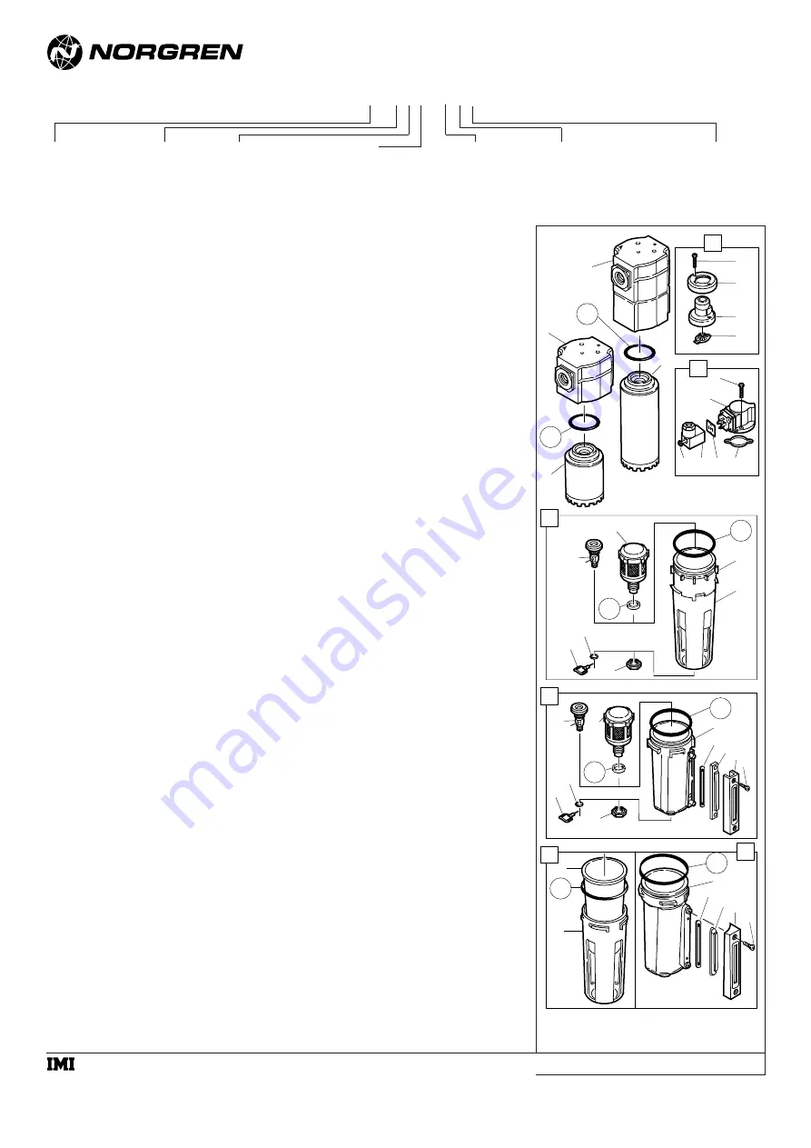
F74CExpldView
2
5
3
4
1
8
11
12
13
14
9
10
50
34
35
36
39
37
38
33
28
31
30
29
32
27
Current Metal Bowl
40
Early Plastic Bowl
Early Metal Bowl 44
49
Current Plastic Bowl
17
26
25
24
23
21
18
20
19
22
45
46
48
47
42
41
43
6
7
51
53
52
54
F74C, F74H
Installation & Maintenance
Instructions
Oil Removal Filter
F74 * - * * * - * * *
Thread Form
A .... PTF
B .... ISO Rc taper
G ... ISO G parallel
Bowl
D ... Metal with liquid level indicator
P .... Transparent with guard
Element
0 .... Coalescing
Drain
A .... Automatic
Q ... Manual, 1/4 turn
Service Indicator
D ... With mechanical service
indicator
E .... With electrical service indicator*
Port
3 .... 3/8"
4 .... 1/2"
6 .... 3/4"
* See Norgren publication IM-900.920 for specifications and electrical wire connections of the optional electric service indicator.
Body and Element
C .... Standard
H ... High flow
a subsidiary of IMI plc
IM-200.105.01
(9/98)
Supersedes 4/98
N ... Without indicator


