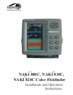
background image

www.northstarnav.com

Explorer 657

Fishfi nder and Chartplotter

Installation and Operation Manual

Summary of Contents for EXPLORER 657

Page 1: ...www northstarnav com Explorer 657 Fishfinder and Chartplotter Installation and Operation Manual ...

Page 2: ...to avoid possible injury or death WARNING WARNINGindicatesapotentiallyhazardoussituationwhich ifnotavoided could result in death or serious injury CAUTION CAUTION indicates a potentially hazardous situation which if not avoided could result in minor or moderate injury CAUTION CAUTION used without the safety alert symbol indicates a potentially hazardous situation which if not avoided may result in...

Page 3: ...e 657 with other plotting sources such as observations depth soundings radar and hand compass bearings Should the information not agree then the discrepancy must be resolved before proceeding any further Important Sonar fishfinder The accuracy of the sonar depth display can be limited by many factors including the type of the transducers the location of the transducers and water conditions It is t...

Page 4: ...6 Simulate mode 13 2 7 The main windows 14 3Navigation Chart 19 3 1 Introduction to navigating 19 3 2 Chart window 21 3 3 Distance and bearing calculator 23 3 4 Projected course 23 3 5 Tracks and tracking 24 4Navigation Highwaywindow 24 5Navigation Waypoints 25 5 1 Waypoints window 25 5 2 Managing waypoints 26 6Navigation Routes 27 6 1 Routes window 28 6 2 Managing routes 28 7Satellites 30 7 1 Sat...

Page 5: ...window 44 11Datawindow 44 12Fuelfunctionsanddisplay 45 12 1 What the fuel computer does 45 12 2 Fuel window 45 12 3 When you add or remove fuel 46 12 4 Low fuel alarm 47 12 5 Boat speed sensors 47 12 6 Fuel consumption curves 49 12 7 Calibration 51 13Tideswindow 52 14Usercardwindow 53 15AIS 54 15 1 Viewing AIS Vessels 55 15 2 Dangerous Vessels 55 15 3 AIS Windows 56 16DSC Buddytrackwindows 57 16 1...

Page 6: ...ssories 75 18 3 Installation The display unit 77 18 4 Installation Power data cable 78 18 5 Installation GPS antenna 79 18 6 Installation Sonar transducer 80 18 7 Installation Northstar petrol gasoline sensors 80 18 8 Installation SmartCraft 81 18 9 Installation Other NavBus instruments 81 18 10 Installation Other NMEA instruments 82 18 11 Installation Setup and test 83 AppendixA Specifications 84...

Page 7: ... of where the boat has been 3 5 GPS receiver status 7 Saving and loading data with a user card 14 User card Chart data Chart features built in world chart 3 2 Chart details 3 2 4 5 C MAP chart Tides at a port 11 C MAP chart AIS 15 Alarms Built in alarms 2 5 SmartCraft engine alarms 1 1 SmartCraft Boat data Data at top of main displays 2 7 3 Compass at top of main displays 2 7 4 Dedicated data wind...

Page 8: ...ansducer free of weed paint and debris Do not use a high pressure water blast on a speed sensor paddlewheel as it may damage the bearings Push the dust cover over the display when the 657 is turned off The Northstar 657 is a compact rugged highly integrated marine chartplotter and fishfinder It is easy to use and has an easy to read color display Complex functions can be performed with a few key p...

Page 9: ...ff see section 2 2 and put the dust cover on 2 Loosen the knob on the mounting bracket and lift the unit off the bracket 3 Unplug the connectors from the display unit turning each locking collar anticlockwise until you can pull the plug out 4 Push the attached dust covers over the exposed ends of the connectors 5 Store the display unit in a dry clean place such as the optional Northstar carry bag ...

Page 10: ...highlight to the command for example Goto cursor then press ESCAPE Go back to an earlier menu or display In chart mode centres chart at boat s position DISPLAY Show a menu of the main displays To go to a display select it from the menu see section 2 7 CURSOR KEYS to move the cursor or the selection highlight MENU Show a menu of the options for the current window Press again to display the Setup me...

Page 11: ...2Turningonandoff autopower Turningonmanually If the 657 is not wired for auto power press to turn the unit on If necessary adjust the display to be easy to read see section 2 3 Note If the 657 is not wired for auto power then the 657 does not record engine hours and might not record fuel consumption see section 18 4 Turningoffmanually If the 657 is not wired for auto power or if the ignition switc...

Page 12: ...to the MOB waypoint Select Yes to immediately start navigating to the MOB waypoint This might result in a sudden and dangerous turn WARNING No disengage the autopilot then use the 657 to manually navigate to the destination MOB waypoint see sections 3 1 1 and 3 1 2 To cancel MOB or set another MOB 1 Press again to display a menu 2 Select an option from the menu Tip The MOB waypoint remains on the ...

Page 13: ...oute and automatically displays different 657 functions To start and stop Simulate mode and for more information see section 17 15 In simulate mode Simulate or Demo flashes at the bottom of the display WARNING Never have Simulate mode on when the 657 is navigating on the water 2 5Alarms When the 657 detects an alarm condition it displays a warning message on the display the internal beeper sounds ...

Page 14: ...ional sensors and instruments that are installed see section 1 1 2 Set up commonly used windows as favorites and press to switch between windows see section 2 7 2 The display menu allows quick access to the main windows Full screen Chart and Sonar are at the top of the menu Other windows are available from the More sub menu ...

Page 15: ...15 Northstar Explorer 657 Installation and Operation Manual Note The windows below the menu divider can only be shown full screen without a data header see section 2 7 3 ...

Page 16: ...1 Press twice to change the active window 2 Press select Replaceand select the second window The 657 exchanges the two windows Replacing a window on the display 1 Press twice to change the active window 2 Press select Replaceand select a new window that is not currently visible Note When some windows are small then not all the data is shown The active window If there is more than one window displa...

Page 17: ...avorite display to the list 1 Set up the display with the window or windows you want in the new favorite see section 2 7 2 Press and select Save this display The 657 displays the favorites list 3 Select where in the list to add the new favorite If you select an existing favorite display then the new favorite will replace the existing favorite in the list 2 7 2Favoritedisplays Deleting a favorite d...

Page 18: ...elect None to leave the field empty iii Repeat the above step to set the other data fields Tip If all fields in a line are None then the line will not be displayed and the data header will take less space on the display 5 Press Tip The data header will change when you select another display To set a data header that you can recall later set the header as part of a favorites display see below Favor...

Page 19: ... the arrival radius alarm is enabled then an alarm will sound to show that the boat has reached the destination see section 17 9 3 1 2Goingtoawaypointortoapointon thechart A waypoint is a position that you can set on the 657 chart for example a fishing spot or a point on a route see section 5 Going to a waypoint from the chart window 1 Go to the chart window 2 Move the cursor to the waypoint eithe...

Page 20: ...ndow 1 Go to the routes window 2 Then follow step 3 as in starting a route from the chart window above Navigating The 657 navigates to each waypoint on the route in turn as described in section 3 1 1 The 657 stops navigating to the waypoint at the end of the current leg and starts the next leg of the route a when the boat comes within 0 025 nm of the waypoint b or when the boat passes the waypoint...

Page 21: ...hart scale see section 3 2 3 D Boat position see section 3 2 1 E Boat track see section 3 5 F Boat course and CDI lines see Appendix C CDI G Distance and bearing of cursor from boat H Land I Sea J The cursor see section 3 2 1 K A typical waypoint see section 5 Note To change the types of information displayed on the chart see section 17 2 To change to a perspective view of the chart see section 3 ...

Page 22: ...dow press The boat is at the center of the chart As the boat moves through the water the chart automatically scrolls to keep the boat in the center of the chart The cursor see below is turned off Cursor mode The keys and are called cursor keys To switch to cursor mode in the chart window hold down a cursor key The cursor appears and moves away from the boat Press the key which points in the direct...

Page 23: ... length of each leg as well as the total distance along the course The completed course can be converted into a route To use the distance and bearing calculator 1 Select the Chart window Press and select Distance 2 Move the cursor to the start of the first leg It does not matter if this point is a waypoint or not Press 3 To add a leg to the course move the cursor to the end of the leg It does not ...

Page 24: ...en recording continues and the oldest points in the track are deleted The maximum length of a track depends on the selected track interval a small interval will give a shorter more detailed track and a long interval will give a longer less detailed track as shown in these examples Time intervals Interval Track 1 Track 2 3 4 or 5 1 sec 33 minutes 8 minutes 10 sec 5 5 hours 1 4 hours 1 min 33 hours ...

Page 25: ...t can sound an alarm see section 17 9 A display option Controls how the waypoint is displayed when the Waypoints setup option is set to Selected see section 17 2 Off The waypoint is not displayed Icon The waypoint icon is displayed I N Icon and Name The waypoint icon and name are displayed If there are many waypoints use this feature to select which waypoints are displayed on the chart Note The ot...

Page 26: ...int see section 5 2 3 and change the latitude and longitude 5 2 3Editingawaypoint Editing a waypoint from the chart window 1 In the chart window move the cursor to the waypoint to edit 2 When the waypoint data is displayed press 3 Change the waypoint data see section 5 2 7 Editing a waypoint from the waypoints window 1 In the waypoints window press or to highlight the waypoint to edit Press and se...

Page 27: ...e 5 2 8SortWaypoints To change how the waypoints list is displayed 1 Press and select Sort by 2 Select how to display the list Name In alphabetical order by name Icon Grouped by icon type Distance In order of distance from the boat An arrow at at the top of a column indicates how the waypoints are sorted 5 2 9Navigatingtoawaypoint See section 3 1 2 6 Navigation Routes A route is a list of waypoint...

Page 28: ...nge the new waypoint data see section 5 2 7 You can not use a Danger waypoint in a route 1 In the chart window press and select New route 2 The route is given a default name i Change the name if necessary ii Select OK 3 To enter the legs of the route i Move the cursor to the start of the route and press ii A waypoint is created with a default name to save this waypoint press enter to edit the wayp...

Page 29: ...rwise select the waypoint to insert the new waypoint in front of ii Press A list of waypoints is displayed Select the waypoint to use As waypoints are inserted the distance and bearing of each leg is shown automatically If the route has more waypoints than will fit on the display press or to see them 5 To remove a waypoint from the route i Select the waypoint to remove ii Press and select Remove 6...

Page 30: ... time WAAS covers all of the USA and most of Canada EGNOS will cover most of Western Europe when it becomes operational 7 Satellites Differential beacon DGPS Differential beacons are land based radio transmitters that broadcast correction signals that can be received by a special receiver on the boat Differential beacons are usually only installed near ports and important waterways and each beacon...

Page 31: ...Sonar functions require an optional sonar transducer to be installed and set up This section explains how to interpret the sonar displays when and why to use the different frequencies and how fish are detected and displayed It also describes Gain and Range and shows examples of some of the different sonar displays 8 1Usingthe657 The 657 uses a sonar transducer attached to the hull The transducer g...

Page 32: ...ocation of the fish or object The area covered by the ultrasonic pulse is a rough cone shape and the echoes are strongest in the middle Clarity of water Particles or air in the water reduce the strength of the echo Composition or density of the object or bottom Note Planing hulls at speed produce air bubbles and turbulent water that bombard the transducer The resulting ultrasonic noise may be pick...

Page 33: ...ands C Hard bottoms such as rock or coral show as wide bands A C B Frequencyandconewidth Water Cone width Cone width Depth at 50 kHz at 200 kHz 25 20 5 50 40 10 100 80 20 150 130 30 200 170 40 300 250 60 400 330 80 600 500 120 800 660 150 1000 830 190 45 cone 11 cone The sonar pulse generated by the 657 transducer travels down through the water spreading outwards in a cone shape The cone width is ...

Page 34: ...ing bottom dwellers Whentouse50kHz The 50 kHz frequency is particularly suitable for use in deep water typically greater than 500 ft 150 m At 50 kHz the cone covers an area of water about four times wider than the 200 kHz cone and penetrates to a greater depth with minimal loss of the return signal However it produces a lower definition display with more shadow compared to the 200 kHz frequency Th...

Page 35: ...y combines the 200 kHz and the 50 kHz echoes on one sonar display filling in detailed echoes in the center of the sonar cone Whentouse50 200kHz Operating the 657 at both 50 kHz and 200 kHz simultaneously on a split display can be very useful when operating in shallow to medium water typically less than 500 ft 150 m because the 50 kHz section of the display shows the general area while the 200 kHz ...

Page 36: ...star Explorer 657 Installation and Operation Manual 36 50kHzdisplay 200kHzdisplay 200 50Khzdisplay Mixeddisplay 1 minute ago 30 seconds ago Now Comparisonofthesamefishscenariodisplayedatdifferentfrequencies ...

Page 37: ...ed ultrasonic pulse is displayed as a fish arch The 50 kHz frequency uses a wider cone than the 200 kHz frequency This makes the fish arches easier to see A fish arch starts when a fish enters the weak edge of the sonar cone generating a weak echo that is displayed as the start of the fish arch As the fish moves closer to the middle of the cone the distance between the transducer and the fish redu...

Page 38: ... Auto mode 1 Go to a sonar display see section 9 2 Press select Range and select Auto Manual The 657 does not adjust the range automatically If the bottom depth is below the range the bottom will not appear on the display Manual range is useful if the bottom depth changes rapidly because Auto range will cause the display to change range frequently To set Manual range or to change the range 1 Go to...

Page 39: ...hoes less than 50 of the maximum signal are ignored There is a separate threshold setting for each sonar frequency 50 kHz and 200 kHz Thegainwindow To display or change the current settings for gain select a sonar display and press Select Threshold to display the thresholds This display is called the gain window Changing mode The 657 has three operating modes In Cruising and Fishing modes the 657 ...

Page 40: ...plit bottom Sonar history plus a bottom trace in a zoomed section see section 9 3 Split 50 200 Sonar histories at 50 and 200 kHz see section 9 4 9 Sonar fishfinding Displays 9 1Sonarhistorydisplay nosplit Split A Scope Sonar history plus echo strength see section 9 5 If the display is split adjust the split ratio if required 1 Press and select Sonar display split 2 Press or to adjust the ratio 3 P...

Page 41: ...f the sonar history The Sonar Zoom display shows the sonar history on the right and the zoomed section on the left The Full Screen Zoom display shows the zoomed section only The zoom bar on the far right shows the area of the history that is magnified in the zoom section Press or to adjust the zoom range the range of depths included in the zoom section If Bottom lock is on the zoom depth the depth...

Page 42: ...jects close to the bottom The zoom bar on the far right shows the area of the history that is magnified in the zoom section Use the or keys to adjust the zoom range The 657 calculates the zoom depth automatically It is not necessary to turn Bottom lock on for this display A Zoomed bottom signal B Sonar history A B 9 4Sonar50 200display The display shows A the 50 kHz sonar history on the left B the...

Page 43: ...nd select 200 kHz or 50 kHz 3 Press select Sonar splits then select Split A scope 4 Press to display the Gain window To adjust gain or threshold for a frequency press or to select the setting to adjust then press or to change the setting 5 Set threshold to zero 6 Adjust Gain so the peak of the strong signal from the bottom just touches the gain line 7 Adjust threshold so that it is just to the rig...

Page 44: ... Select the layout to change see above 2 Press and select Gauge setup 3 Highlight the gauge to change Press and select the data to display in the gauge 4 Repeat the above step to change other gauges 5 Press 11 Data window The data window has large numeric data fields and a graph of depth and water temperature if available To go to the data window press select More then select Data To select what d...

Page 45: ...or to measure speed calibrate it during installation or if the speed readings seem inaccurate 12 2Fuelwindow To go to the Fuel window press select More then select Fuel The display differs according to the number of engines and tanks If engine RPM is available and if you have made and selected a Fuel Consumption Curve see section 12 6 press to switch between a Summary or a Fuel curve display TheFu...

Page 46: ... will be meaningless A When you completely fill a tank Go to the fuel window and press Then On a single tank boat select Fill tank On a multi tank boat select Fill tank then select the tank you have filled Note Underfloor fuel tanks are often difficult to refill to the same level twice due to air pockets With underfloor fuel tanks Trim the boat to the same angle in the water each time you follow p...

Page 47: ... fuel level to trigger the low fuel alarm 12 4Lowfuelalarm When a low fuel alarm is set the alarm s fuel level is shown on the fuel window tank levels as a red bar The alarm can also be set using the Alarms setup menu see section 17 9 12 5 1Selectingaboatspeedsensor The fuel calculations can use boat speeds from the GPS or from a paddlewheel sensor or pitot sensor if these optional sensors are ins...

Page 48: ...12 5 1 When the current is from ahead ground speed is less than water speed For this example If the boat travels for one hour uses 3 gallons of fuel per hour and has 50 gallons of fuel left Speed Log Economy Range Using water speed 10 knots 10 nm 3 3 nm gal 165 nm Using ground speed 6 knots 6 nm 2 0 nm gal 100 nm Water speed 10 knots Gives a ground speed of about 8 knots Current 4 knots at 45º Whe...

Page 49: ... for the curve see section 12 5 1 Normally choose Water speed to measure the boat s potential performance 3 Press twice then select Fuel 4 Select Fuel consumption curve then select New 5 Enter the comfortable maximum RPM you know you can achieve for the engine rather than the maker s value 6 The 657 then asks you to set the minimum RPM Set the throttle to idle on a multi engine boat set all engine...

Page 50: ...e of speed sensor you selected when making the curve see sections 12 5 1 and 12 5 Using a curve C D E F A B Compare your boat s performance now at the current RPMs with the boat s performance when you made the curve You can compare your boat s performance now with a curve made under ideal conditions or with a curve made under similar conditions Information in a curve A RPM of the boat now For a tw...

Page 51: ...ficult to fill underfloor tanks to the same level twice due to air pockets so the more fuel used the more accurate the calibration 12 7Calibration To calibrate the sensor s 1 Record the level of the fuel in the tank s 2 Connect the portable tank s to the engine through the fuel sensor s 3 Run the engine at normal cruising speed until at least 4 gallons 15 litres of fuel has been used per engine 4 ...

Page 52: ...Press and select Chart info 5 Select Tide height Choosing the date of the tide chart 1 Press 2 Select Today Next day or Prev day To choose a different date from these select Set date edit the date press A Tide station name and distance from boat B Current time and chosen date for display C Tide chart D Night E Dawn F Day G Dusk H Tide height I Time cursor a vertical dotted line Press or to move cu...

Page 53: ...oaded into the 657 with the LOAD command see below Savingdatatotheusercard This saves all the 657 s waypoints all the 657 s routes or one of the 657 s tracks to one file on the user card 1 Press and select Save 2 Select Waypts Routes or Tracks 3 For Tracks select the track number to save 4 The new file is created Change the name if required The new file appears in the file list Loadingdatafromtheu...

Page 54: ...rmat a chart card 15 AIS AIS is short for Automatic Identification System The International Convention for Safety of Life At Sea SOLAS requires all vessels greater than 300 tons and all passenger vessels to be equipped with AIS Transponders All vessels equipped with AIS permanently broadcast via one or more of the two dedicated VHF channels This transmission may include information about the vesse...

Page 55: ...sel place the cursor over an AIS vessel for at least two seconds and press Press either or to clear the information 15 2DangerousVessels The 657 calculates the time of closest point of approach TCPA and closest point of approach CPA for each AIS vessel This is used to determine potential dangerous vessels If the TCPA and the CPA is below the trigger values then it will be considered dangerous See ...

Page 56: ...e last message DisplayinganAISvesselonthechart 1 Press or to select a vessel 2 Press and select Display The Instrument switches to chart window with the selected vessel position in the middle DisplayingFullAISDetails 1 Press or to select a vessel 2 Press and select More Info or press This window displays all information for the selected AIS vessel provided by the AIS receiver SortingVessels Press ...

Page 57: ...isplays Distress Poll or Buddy track If there are more items than will fit on the display press or to see the others 16 1Thedisplays Distress Boats that have sent DSC distress messages and their positions Poll Boats you have manually polled on the VHF radio and their position at that time Buddytrack Buddy boats from your DSC radio The radio regularly calls the boats and updates their positions Whe...

Page 58: ...nd select Edit waypoint Edit the waypoint data if required see section 5 2 7 Deletingaboat At the Distress or Poll displays 1 Press or to select a boat 2 Press and select Delete The boat is deleted from that display Delete any boat waypoint manually see section 5 2 5 Buddy track boats automatically disappear from the Buddy track window when your DSC radio can not pick up their signal Deletingallbo...

Page 59: ...miliar with the operation of the unit using the default settings before making any changes in these menus To go to a setup option menu press twice then select an option Note 1 The Setup menu options are explained in the following sections 2 Section 2 1 describes how to set or change data in the setup menus 3 The setup data available will depend on the optional sensors and instruments installed ...

Page 60: ...nd instruments installed System see 17 1 Chart see 17 2 Sonar see 17 3 Favorites see 17 14 Time see 17 13 Alarms see 17 9 Units see 17 10 Comms see 17 11 Logs see 17 8 Track see 17 6 Fuel see 17 5 GPS see 17 4 Calibrate see 17 12 Simulate see 17 15 General Water Land and Other submenus 17 2 SmartCraft See the SmartCraft Gateway Installation and Operation Manual AIS see 17 7 ...

Page 61: ...nd routes to the default factory settings shown on the setup menus Aboutwindow The about window shows The software version and date The world chart version Any card fitted 17 1Setup System The number of waypoints routes and tracks you have stored Connector wiring information In the unlikely event of having to contact a Northstar dealer for service quote the software version number and date Sonar D...

Page 62: ...preserve night vision Mapdatum 657 GPS positions are based on a worldwide reference datum known as WGS 84 Most paper charts are based on WGS 84 However some paper charts are based on other datums In these cases the latitude and longitude coordinates of objects on the 657 chart window are different to the latitude and longitude coordinates of these objects on the paper chart This applies to all obj...

Page 63: ...ndow remain unchanged Applying a map shift 1 Move the boat to a known point on the chart for example a marina berth 2 In the Chart setup menu select Map shift 3 Move the cursor to the position on the chart where the boat actually is 4 Press and select Set 5 Press to set the new map shift The boat will now be displayed at its actual location Clearing the map shift Clearing the map shift removes any...

Page 64: ...h for Bathymetrics and Spot soundings Tidal flow Displays dynamic tide flows arrows on a chart showing the present tide stream and orientation requires a GPS fix and an NT MAX card Land submenu Land features Displays land features for example regions rivers roads railways airports Land elevation Displays land contours shaded like depths requires an NT Max card Other submenu Waypoints Displays waypo...

Page 65: ...y more fish symbols Digitsize Use this to remove or change the size of the depth window on the sonar displays There is a choice of Small Medium and Large Palette Use this to select a color palette Each color within the palette represents a different echo strength as shown on the sonar displays There is a choice of five color palettes Black Blue White Vivid and 8 color The first four pallettes disp...

Page 66: ...r for servicing or troubleshooting The GPS receiver takes up to three minutes to restart The satellite window shows the status of the GPS receiver see section 7 Restart the GPS if the receiver has not been used for some time and is taking a long time to get a GPS fix StaticNavigation When the boat stops or moves very slowly the calculated GPS speed and course become erratic Static navigation allow...

Page 67: ...low filter can be set from 0 to 30 seconds Use the lowest value which gives a stable flow Usually a value of 5 to 10 seconds will give a satisfactory result for two stroke carburettor engines Fuel injected or four stroke engines may require a larger value This setting affects the Fuel flow and Fuel economy reading on the Fuel window but it does not affect the Fuel used reading Setup tanks If the b...

Page 68: ... to 5 select a track number The selected track is shown on the chart PlottingInterval Select the plotting and recording interval The options are Distance or Time Distance Select the distance plotting interval 0 01 0 05 0 1 0 5 1 0 2 0 5 0 or 10 0 distance units Time Select the time plotting interval 1 5 10 or 30 seconds or 1 minute Memoryused The percentage of memory used in the track being record...

Page 69: ...adius selected from our current position is filtered off the chart Default value is set to 300 nm allowing all vessels to be displayed onto the chart within that distance Filterbyspeed Vessels with speed below value selected by user is filtered off the charts Default is set to 0 kn allowing all vessels to be displayed onto the chart ShowDangerousOnly Show vessels that have a TCPA CPA below the tri...

Page 70: ...radius Boat is closer to the destination or to a waypoint than the alarm trigger value Anchor alarm Boat moves by more than the alarm trigger value XTE Boat moves off course by more than the CDI scale see section 14 2 Danger Boat comes closer to a danger waypoint than the alarm trigger value Loss of DGPS fix 657 can not receive the DGPS signal beacon WAAS or EGNOS Loss of GPS fix 657 can not receive ...

Page 71: ...nnected to other Northstar instruments through NavBus or any compatible NMEA instrument Press twice then select Comms NMEAout NMEA is generally used with third party instruments see section 18 10 Select this to transmit NMEA sentences for example to an autopilot NMEAdata Use this to specify which NMEA sentences will be transmitted see section 18 10 and Appendix A 17 11Setup Comms Lat londps Select...

Page 72: ... Waves and wind cause the boat speed from the paddlewheel transducer to fluctuate slightly To give stable readings the 657 calculates these values by taking several measurements and averaging them Set the Speed filter to the lowest value which gives stable readings The range is 1 to 30 seconds or Off 0 Temperature The factory settings should be sufficiently accurate for normal usage To calibrate t...

Page 73: ... the depths of clear water below the boat enter minus the depth of the deepest part of the boat below the transducer Speedrange The maximum reading to display on an analog boat speed gauge see section 10 Choose a range suitable for your boat Press twice then select Time Localoffset The difference between local time and UTC GMT Change local offset when daylight saving time starts and ends The range...

Page 74: ...terminals are in wet area If the cables supplied are too long do not shorten the cable instead coil the cable Most cables can be extended with Northstar extension cables Do not fit more than one extension cable Correct installation is critical to the performance of the unit It is vital to read the entire installation section of this manual and the documentation that comes with the antenna and any ...

Page 75: ...ion Manual Optionalsensorsandinstruments External alarms Lights or sounders in the boat to sound alarms through the boat see section 18 4 GPS or DGPS antenna For GPS navigation see section 18 5 Sonar transducer For depth sounding and fish finding see section 18 6 18 2Installation OptionsandAccessories Fuel sensors For fuel functions The 657 can use these optional fuel flow sensors fitted to one or...

Page 76: ... sensors 18 7 NMEA in 18 10 Sonar transducer 18 6 Display unit 18 3 Power data cable Pin Wire Function 1 Black Ground power in NMEA ground The cable has two black wires which are connected inside the cable and it does not matter which black wire you use 2 Brown Not used 3 White NMEA out 4 Blue NavBus 5 Red Power in 10 5 V DC to 30 5 V DC 6 Orange NavBus 7 Yellow Auto power in 8 Green External alar...

Page 77: ...from the compass at least 12 300 mm away from any radio transmitter and at least 4 ft 1 2 m away from any antenna Easy to read and operate If possible mount the display unit in front of the navigator or to the right of the navigator because the LCD display is more readable from these positions 2BracketMounting Requires a panel for mounting the bracket Ensure that the panel is not likely to deform ...

Page 78: ...wer data cable to the black display unit connector turn the collar to lock the connector Black Black Power data cable Red Yellow Black 18 4Installation Power datacable Main switch 12 24 V DC Fuse 2A The power data cable has a black locking collar and flying leads 1 Wire the 657 for auto power to have the 657 turn on with the boat s ignition switch or to to record engine hours or if the 657 must ad...

Page 79: ...enna Fit one of these GPS antennas Normally use the GPS antenna supplied An optional differential beacon DGPS antenna to give enhanced accuracy within range of land based differential beacons in areas where WAAS or EGNOS are not available Such a DGPS antenna has both a GPS receiver and a beacon receiver and it automatically applies the beacon correction to the GPS position A compatible GPS or DGPS...

Page 80: ...NING Do not install plastic through hull transducers in solid wooden hulls Leakage through the hull may result Do not install bronze transducers in metal hulls This will cause electrolytic corrosion that may result in damage to the hull or transducer Blue Sonar cable 18 7Installation Northstarpetrol gasolinesensors Fit the optional petrol gasoline fuel kit following the instructions supplied with ...

Page 81: ...the units alarms or calibration are changed in one instrument then the values will automatically change in all other instruments of the same type Each instrument can be assigned to a group of instruments If the backlight is changed in an instrument in group 1 2 3 or 4 then the backlight will automatically change in the other instruments in the same group If the backlight is changed in an instrumen...

Page 82: ...Receive data from an optional AIS receiver For information on sending NMEA data to the 657 see your Northstar dealer During setup to send NMEA data to other instruments set NMEA out to and specify the NMEA data to send see section 17 11 Black Power data cable Yellow White NMEA out Black NMEA ground GPS antenna White NMEA in requires Special Fuel Cable Yellow GPS fuel AIS cable White Red AIS data i...

Page 83: ...ays an installation menu i Select the language to use ii Change the data if necessary see section 2 1 iii When the setup data is correct press This data can be changed later see section 17 18 11Installation Setupandtest 5 Enter setup data to set up the 657 to your requirements and to set up any optional sensors or instruments see section 17 6 At the satellite display check that it picks up GPS sat...

Page 84: ...dependent down to 0 01 nm in plotter mode SONAR FISHFINDING Depth range 0 6 m 2 ft to 1000 m 3300 ft Sonar output Power Variable up to 600 W RMS Dual frequency 50 khz and 200 kHz Transom transducer cable length 10 m 33 ft Depth acquisition time from startup Typically 2 seconds at 30 m 100 ft Temperature Range 0 to 37 7 C 32 to 99 9 F Resolution of 0 1 unit Speed from paddlewheel transducer 1 to 96...

Page 85: ...and 1965 ISTS 061 Astro 1968 ISTS 073 Astro 1969 Johnston Island 1961 Kandawala Kerguelen Island 1949 Kertau 1948 Kusaie Astro 1951 L C 5 Astro 1961 Leigon Liberia 1964 Luzon M Poraloko Mahe 1971 Massawa Merchich Midway Astro 1961 Minna Montserrat Island Astro 1958 Nahrwan Masirah Is Oman Nahrwan United Arab Emirates Nahrwan Saudi Arabia Naparima BWI North American 1927 North American 1983 North S...

Page 86: ...y be corroded Test the fuse or replace it with a fuse known to be good Appendix B Troubleshooting This troubleshooting guide is written with the assumption that the user has read and understood the relevant sections in this manual It is possible in many cases to solve difficulties without having to send the display unit back to the manufacturer for repair Please follow this troubleshooting section...

Page 87: ...d when daylight saving time starts or ends 2 6Autopilot not responding to 657 no NMEA output a NMEA output disabled or the required NMEA sentences are not turned on Check NMEA settings see section 17 10 b Check that the instrument is connected correctly 2 7 No DGPS fix or loss of DGPS fix a To receive a DGPS fix WAAS EGNOS must be enabled or an optional DGPS antenna fitted see section 7 b With WAA...

Page 88: ...le underway with debris etc If the transducer has been impacted it may have been kicked up on the bracket If it is not physically damaged reset the transducer back to its original position See the Transom Transducer Installation Guide c When the transducer is less that 2 ft 0 6 m from the bottom the depth readings may become inconsistent and erratic d Manual Gain may be set too low which may cause...

Page 89: ...moving a Ensure the back of the bottom surface of the transducer is slightly lower than the front and the front is as deep in the water as possible in order to minimise the generation of bubbles through cavitation See the Transom Transducers Installation Guide for more information b The transducer may be in turbulent water Air bubbles in the water disrupt the echoes returned interfering with the 6...

Page 90: ...on 3 1 GPS Global Positioning System A satellite based navigation tool see section 7 Leg The straight segments of a route between waypoints A route with four waypoints has three legs MMSI Maritime Mobile Service Identity Unique identification number for a vessel for use in Digital Selective Calling MOB Man overboard MOB function Starts navigating back to the place where someone fell overboard see ...

Page 91: ...d see section 17 9 an alarm will sound if the boat reaches a CDI line COG Course Over Ground Direction in which the boat is moving over the ground CTS Course To Steer Optimum course to steer to return to the plotted course DTG Distance To Go Distance from the boat to the destination ETA Expected Time of Arrival At the destination assuming that SOG and COG remain constant DST Distance from boat to ...

Page 92: ...VSZ 3PBE DUPO 64 1I 1I BY TBMFT COUNBSJOF DPN 6301 6OJU 0DFBO 2VBZ FMWJEFSF 3E 4PVUIBNQUPO 40 2 1I BY OPSUITUBSVL OPSUITUBSOBW DPN 6453 10 PY MBEFTWJMMF 48 6453 1I BY OPSUITUBSBVT OPSUITUBSOBW DPN 8 10 PY FXUPO VDLMBOE VDLMBOE 8 1I BY OPSUITUBSO OPSUITUBSOBW DPN ...

Reviews: