background image

NOVATECH INSTRUMENTS

1

Rev 1.01,  

425A Manual

INSTRUCTION MANUAL

Precision 350 MHz Synthesizer

Model 425A

Table of Contents

 Section

Page

Contents

1.0  . . . . . . . . . . . . . . . . . . . . . . . . . . . . . 2  . . . . . . . . . . . . . . . . . . . . . . . . .  Description
2.0  . . . . . . . . . . . . . . . . . . . . . . . . . . . . . 2  . . . . . . . . . . . . . . . . . . . . . . .  Specifications
3.0  . . . . . . . . . . . . . . . . . . . . . . . . . . . . . 3  . . . . . . . . . . . . . . . . . Hardware Installation
4.0  . . . . . . . . . . . . . . . . . . . . . . . . . . . . . 3  . . . . . . . . . . . . . . . . . . . . . . . . . . .Operation
5.0  . . . . . . . . . . . . . . . . . . . . . . . . . . . . . 6  . . . . . . . . . . . . . . . . . . Theory of Operation
6.0  . . . . . . . . . . . . . . . . . . . . . . . . . . . . . 7  . . . . . . . . . . . . . . . . . . . .  Performance Test
7.0  . . . . . . . . . . . . . . . . . . . . . . . . . . . . . 8  . . . . . . . . . . . . . . . . . . . . . . . . . .Calibration

--. . . . . . . . . . . . . . . . . . . . . . . . . . . . . . .10


. . . . . . . . . . . . . . . . . . . . . . . . . . .


Warranty

--. . . . . . . . . . . . . . . . . . . . . . . . . . . . . . .10


. . . . . . . . . . . . . . . . . . . . . 

Option E, Errata

Summary of Contents for 425A

Page 1: ...Precision 350 MHz Synthesizer Model 425A Table of Contents Section Page Contents 1 0 2 Description 2 0 2 Specifications 3 0 3 Hardware Installation 4 0 3 Operation 5 0 6 Theory of Operation 6 0 7 Per...

Page 2: ...AMPLITUDE VOL 0 5 V VOH 2 0 V into a series terminated load Tr f 2 5 ns Duty Factor 40 60 divider off 50 Programmable 16 bit divider with a selectable 2 prescaler allows LVCMOS frequencies below 2 Hz...

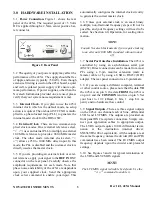
Page 3: ...ck select command to enable your input This automatically configures the internal clock circuitry to generate the correct master clock 3 6 Unless your external clock is an exact binary multiple non fr...

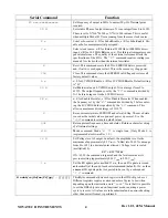
Page 4: ...Prescaler When enabled the frequency set by the F0 command is divided by 2 before enter ing the LVCMOS divider specified by the D0 command This allows a maximum divide integer of 131072 S Saves curren...

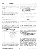
Page 5: ...Hz reference 940 0 MHz internal master clock your frequency setting would be Fsetting Fdesired 0 998138215286 MHz Fsetting 9 98138215286 send F0 9 98138215286 4 9 When used with an external clock of 2...

Page 6: ...ide of 3 DO 2 will result in a 33 duty factor Even values produce symmetrical duty cycle outputs The pres caler setting does not affect the duty factor since it is before the programmable divider 4 17...

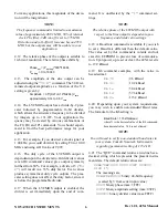
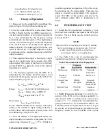
Page 7: ...stomer s input setting scaled by a factor of three and converted to a binary value with the LSB having a weight of 10 Hz 5 5 Since the DDS IC is a sampled data system the output frequency is limited t...

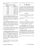
Page 8: ...proper scaling per Section 4 6 9 This concludes the verification test of the 425A 7 0 CALIBRATION 7 1 The 425A has two user adjustable components Y2 frequency and R37 output amplitude Calibra tion sh...

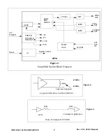
Page 9: ...POWER FILTERS 5V 5V Master Clock EXT CLK IN CLK SEL Figure 2 Simplified System Block Diagram 425A Serial C System Control 1 8V REGULATOR AD9912 5V 3 3V Buffer LVDS OUT 100 Typical LVDS Driver SN65LVD...

Page 10: ...g or repairing defective instruments that have been returned by purchaser at the purchaser s expense to NOVATECH INSTRUMENTS and that have not been subjected to misuse neglect improper installation re...

Reviews: