

1
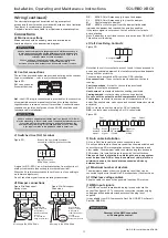
Code description example
S* (T) (NC) -XB*-* * 2WP
| |
|
| | | |
|
1
2
3
45 6 7
8
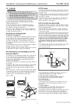
1.
1 = Unit size 2 to 10.
2. T = Optional Twin (run & standby) extract fan; available as
vertical stacked XBV for sizes S2 - 6T and S8T or horizontal
XBH for size S8T.
3.
Ecosmart control as standard. NC = optional no control version,
FC = optional fan speed control only.
4. V = Vertically stacked unit, H = side-by-side unit (available for
S6 to S10 only).
5. L = Left hand, R = right hand (see illustrations).
6. E = Electric heater (sizes 2 to 8 inclusive), L = LPHW coil,
N = No heater fitted.
7.
2 = 2 row heating coil.
8. WP = Optional weatherproof cover.
Example: S2-XBV-LE is size 2, vertically stacked with electric heater
and left hand access.
S6NC-XBH-RL is a size 6 with no controls, horizontal side-by-side
unit, right hand access and LPHW heating coil.
SQURBO XBOX
(Pre-packaged heat recovery unit)
Installation, Operating and
Maintenance Instructions
The EMC Directive
20
1
4/
30
/E
U
The Low Voltage
directive
20
14
/
35
/E
U
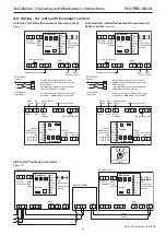
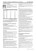
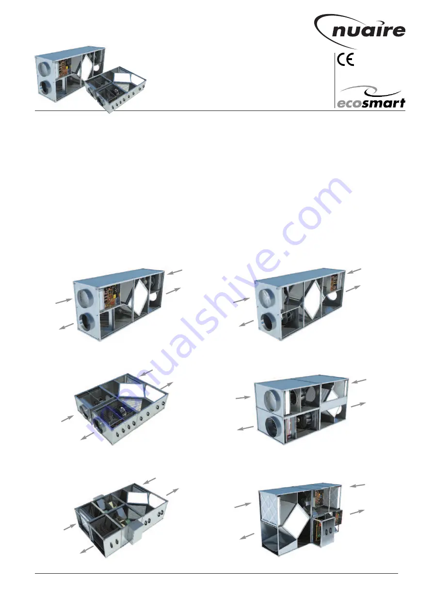
Figure 2: S2/5-XBV-RN (right hand with no heater).
Figure 1: S2/5-XBV-LE (left hand with electric heater).
Nuaire Limited
Western Industrial Estate Caerphilly United Kingdom CF83 1NA
T: 029 2085 8400 F: 029 2085 8444 E: info@nuaire.co.uk W: www.nuaire.co.uk
08. 06. 18. Leaflet Number 671408
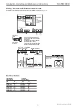
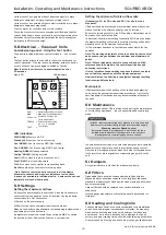
Figure 5: S7/8-XBH-RE (right hand with electric heater).5
Intake
Exhaust
Extract
Supply
Figure 3: S6-XBH-RE (right hand with electric heater).
Intake
Exhaust
Extract
Supply
Figure 4: S6-XBV-LE (left hand with electric heater).
Supply
Extract
Exhaust
Intake
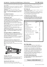
Figure 6: S7/8-XBV-RL (right hand with LPHW).
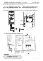
AHU with Heat Recovery section and direct drive AC motor technology.
AHU with Heat Recovery section and direct drive EC motor technology.
AHU with Heat Recovery section and direct drive AC motor/Inverter technology.
Supply
Extract
Exhaust
Intake
Exhaust
Intake
Supply
Extract
Exhaust
Intake
Supply
Extract


