background image

It is of vital importance, before attempting to 
operate your engine, to read the general 
'SAFETY INSTRUCTIONS AND WARNINGS' 
section on pages 2-6 of this booklet and to strictly 
adhere to the advice contained therein.

Also, please study the entire contents of this 
instruction manual, so as to familiarize yourself 
with the controls and other features of the 
engine.

Keep these instructions in a safe place so that 
you may readily refer to them whenever 
necessary.

It is suggested that any instructions supplied 
with the aircraft, radio control equipment, etc., 
are accessible for checking at the same time.

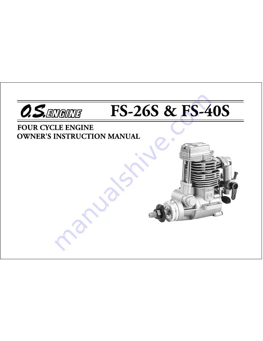
Summary of Contents for FS-40S

Page 1: ...ntained therein Also please study the entire contents of this instruction manual so as to familiarize yourself with the controls and other features of the engine Keep these instructions in a safe plac...

Page 2: ...SILENCER LINKAGE OF THROTTLE LEVER BEFORE STARTING FUEL AND PRESSURE LINES ADVICE ON SELECTION OF FUEL GLOEPLUG PROPELLER STARTING THE ENGINE CONTENTS RUNNING IN CARBURETOR CARBURETOR AIR BLEED ADJUST...

Page 3: ...would respectfully request that these instructions are also passed on to its new owner SAFETY INSTRUCTIONS AND WARNINGS ABOUT YOUR O S ENGINE The advice which follows is grouped under two headings ac...

Page 4: ...ad or exhaust header pipe in particular may result in a serious burn Never touch or allow any object to come into contact with the rotating propeller and do not crouch over the engine when it is runni...

Page 5: ...ring Such noise is also likely to cause annoyance to others over a wide area Install a top quality propeller of the diameter and pitch specified for the engine and aircraft Locate the propeller on the...

Page 6: ...e wearing of safety glasses is also strongly recommended Discard any propeller which has become split cracked nicked or otherwise rendered unsafe Never attempt to repair such a propeller destroy it Do...

Page 7: ...sand The propeller may throw such material in your face and eyes and cause injury For their safety keep all onlookers especially small children well back at least 20 feet or 6 meters when preparing yo...

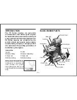
Page 8: ...ngines for model aircraft use and are the outcome of a long period of technical development The FS Series engines are produced by the world s oldest and largest model engine manufacturing company a co...

Page 9: ...surfaces as necessary INCORRECT Top surfaces are not in the same plane Opposite beam Top surfaces are not in the same plane Engine does not rest firmly Rigid hardwood e g maple At least 15mm 19 32 fo...

Page 10: ...needle valve may be adjusted from the outside Cut the L shaped rod supplied to the required length insert it into needle s centre hole and secure it by tightening the set screw in the needle valve kn...

Page 11: ...locknut firmly Re check tightness of locknuts when engine is hot LINKAGE OF THROTTLE LEVER First ensure that the throttle rotor is fully closed when the throttle lever is in the closed position Adjust...

Page 12: ...rome wire while the battery is connected 5 Plug wrench Used for tightening glowplug The O S long plug wrench is available as an optional accessory For tightening glowplug Battery leads 6 Battery leads...

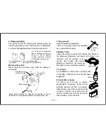
Page 13: ...ne tubing as illustrated after installing the engine Attention to tank height Note When cutting silicone tubing Locate the fuel tank so the top of the tank is 5 10mm 1 4 3 8 above the level of theneed...

Page 14: ...fuel is used the engine should be checked out to make sure that it is sufficiently run in to operate on that particular fuel without overheating Do not use fuels containing less than 18 lubricant ADVI...

Page 15: ...rpm theplugbecomecoolerand ignition is retarded FS 40S 9x6 7 10x6 10 5x6 8x6 3blade 10x7 7 5 11x6 9x7 3blade 10x7 10 5x6 11x7 12x5 6 10x7 3blade Install a plug suitable for the engine Use fuel contain...

Page 16: ...To prevent this from happening even if the propeller itself should slip or loosen it is recommended to use the special Propeller Locknut Set optional extra with the FS 40S Wrench Tighten the propelle...

Page 17: ...he position of the mark or set screw at this time Set screw Turn the needle valve in the direction of arrow from the closed position FS 26S 3 to 3 1 2 turns FS 40S 2 1 2 to 3 turns 6 Open the throttle...

Page 18: ...that it cannot move forward when the engine starts Be careful not to be hit by propeller Fully opened position Fully closed position Set at this Position Starting battery Connect battery leads as sho...

Page 19: ...opeller 12 Engine starts In the interests of safety keep your face and other parts of the body away from the vicinity of the propeller Listen to the sound carefully 13 Needle valve adjustment 1 Slowly...

Page 20: ...the speed of the engine does not instantly change with needle valve readjustment small movements with pauses between are necessary to arrive at the optimum setting 16 Needle valve adjustment Summary P...

Page 21: ...edle valve setting has been established see Needle valve adjustment Summary the procedure for starting is simplified as follows 1 Open the needle valve one half turn 180 from the optimum setting 2 Ope...

Page 22: ...aid of the finest modern precisionmachineryandfromthebestandmostsuitable materials only a very short and simple running in procedure is required and can be carried out with the engine installed in the...

Page 23: ...ne to be varied proportionally from idling speed to full power The carburettor of your engine has been factory set for the approximate best results and no adjustment except to the needle valve should...

Page 24: ...e engine stop Apply full throttle Does the engine regain full power immediately OK Refer to the CARBURETTOR AIR BLEED ADJUSTMENT section on page 24 Re set the idling position at a little higher r p m...

Page 25: ...gain Stop the engine Stop the engine Note Stop engine by pinching fuel line Do not touch needle valve Open air bleed screw Half turn at a time Close air bleed screw Half turn at a time Pre Flight Chec...

Page 26: ...referring to 7 Priming Sluggish rotation Glowplug battery discharged Glowplug element is burned out Something wrong with battery leads Engine flooded due to excessive priming Insufficient priming Eng...

Page 27: ...cedure referring to 7 Priming Close needle valve half turn 180 and wait for several minutes then re start Priming is not necessary Make sure that tank is filled with fuel Check that there is not somet...

Page 28: ...m Wrench 5mm Note Valve clearances of all O S four stroke cycle engines must be checked and reset ONLY WHEN THE ENGINE IS COLD Procedure is as follows Remove the cover from the rocker box on top of th...

Page 29: ...djust the clearance if the engine runs satisfactorily Fig 1 0 04mm Feeler Gauge Rocker Arm Valve 2 If a clearance is found to be outside either of these limits it should be reset as follows Carefully...

Page 30: ...d Fig 5 Tighten Locknut Remove 0 04mm feeler rotate prop through two revolutions and recheck gap 5 If clearance is correct loosen the locknut on the other rocker arm and repeat steps 1 to 5 above Fina...

Page 31: ...gine at the conclusion of a flying session it may cause corrosion The best practice is to disconnect the fuel line from the carburettor while the engine is running Remaining fuel in the tank should al...

Page 32: ...1 cc 0 269 cu in 18 5mm 0 728 in 16 4mm 0 648 in 2 200 12 000 r p m 0 41 bhp 11 000 r p m 268g 9 45 oz FS 26S FS 40S FS 26S FS 40S THREE VIEW DRAWING Dimension mm Specification Displacement Bore Strok...

Page 33: ...6X7 a s d f y t r e w q 7 4 3 2 1 5 4 5 3 5 2 4 1 4 2 3 2 3 1 5 6 1 2 2 5 1 i u o p 8 1 y 1 g FS 26S ENGINE EXPLODED VIEW Type of screw C Cap Screw B Binding Head Screw M Oval Fillister Head Screw F...

Page 34: ...ion Code No Screw Set Rocker Cover Rocker Support Assembly Rocker Support Rocker Arm Retainer 2pcs Rocker Arm Assembly 1pair Rocker Arm 1pc Tappet Adjusting Screw Valve Assembly 1pair Intake Valve 1pc...

Page 35: ...C M2 6X12 C M3X8 C M2 6X7 y t r e w q 7 4 3 2 1 5 4 5 3 5 2 4 1 4 2 3 2 3 1 5 6 5 1 i u 8 1 FS 40S ENGINE EXPLODED VIEW Type of screw C Cap Screw B Binding Head Screw M Oval Fillister Head Screw F Fla...

Page 36: ...Push Rod Cover O Ring 2pcs Cam Follower 2pcs Crankshaft Ball Bearing Front Drive Hub Propeller Washer Propellern Nut Silencer Assembly Silencer Exhaust Header Pipe Glow Plug Type F 4 5225 010 4 5225 0...

Page 37: ...illister head Screw F Flat Head Screw N Round Head Screw S Set Screw Specifications are subject to alteration for improvement without notice Description Code No Throttle Lever Assembly Throttle Lever...

Page 38: ...28 23024008 For 40S 45810100 For 40S 1010A 72108300 1010B 72108310 72200060 PARTS ACCESSORIES Radial Mount Set O S Glow Plug TYPE F Flexible Exhaust Pipes Spinner Nut NON BUBBLE Weight Propeller Lockn...

Page 39: ...MEMO 38...

Page 40: ...hts reserved Printed in Japan U N EQUALLED QUALITY PRECISION PERFORMAN C E ESTABLISHING THE STANDARDS OF EXCELLENC E 110101 TEL 06 6702 0225 FAX 06 6704 2722 6 15 3 Chome Imagawa Higashisumiyoshi ku O...

Reviews: