background image

01/2018 EN

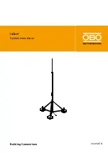
isCon

®

System instructions

Building Connections

Summary of Contents for isCon BA 45 SW

Page 1: ...01 2018 EN isCon System instructions Building Connections...

Page 2: ...OBO Bettermann GmbH Co KG Reprinting even of extracts as well as photographic or electronic reproduction are prohibited isCon is a registered brand of OBO Bettermann GmbH Co KG OBO isCon System instru...

Page 3: ...tem 28 5 1 Cutting and removing the insulation of the isCon conductor 28 5 1 1 Removing the light grey protective jacket isCon ProPI 75 LGR 28 5 1 2 Revealing the copper core for connection 29 5 2 Mou...

Page 4: ...protection ring conductor 58 6 2 Metallic roof parapet 59 6 3 Internal and external isCon conductor 61 6 4 Lightning protection class I 62 6 5 isCon conductor included in the ring conductor 63 7 Check...

Page 5: ...s supplied with the isCon system safe so that the information is available should you need it We will not accept any warranty claims for damage caused through non observance of these instructions Regi...

Page 6: ...fy the agreement with the named standards and stored documents but do not however contain any guar antee of properties You can find individual proofs for lightning protection components on the OBO web...

Page 7: ...through which power is flowing Wear suitable protective clothing and comply with all the required safety guidelines To install the OBO isCon system use only components of the OBO product range as othe...

Page 8: ...t in solid matter This means that installation is possible directly on metallic and electrical structures If there is a direct lightning strike the incoming energy is arrested through the isCon conduc...

Page 9: ...on conductor is also suitable for routing in the earth It can also be painted e g with the paint of the facade As the external light grey protective jacket is non conductive it must be removed in the...

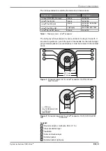
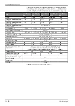
Page 10: ...nductor multi wire Cu 35 mm2 Conductor weight 0 570 kg m 0 570 kg m 0 694 kg m 0 868 kg m 0 666 kg m Temperature range for routing min 5 C max 40 C Operating temperature min 30 C max 70 C Bend radius...

Page 11: ...EN 11 Product description isCon 1 2 Figure 3 isCon conductor in the air termination rod with internal connection ele ment 1 type isCon IN connect isCon IN con PRE isCon IN con 2 and isCon connection...

Page 12: ...ts Legend 1 Air termination rod 2 Insulated central rod 3 Retaining rod The metallic components of the rods are made of aluminium and stainless steel V2A The insulated central rod is made of glass fib...

Page 13: ...5408 938 4 000 50 Alu GRP 1 isFang 3B 100 A isFang IN A 6000 5408 940 6 000 50 Alu GRP isFang 3B 150 A isFang IN A 8000 5408 888 8 000 50 Alu GRP isFang 3B 250 A isFang IN A 10000 5408 890 10 000 50...

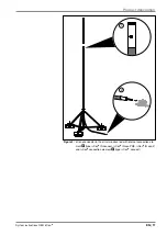
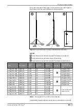
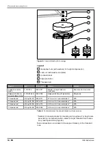
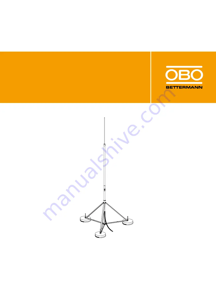
Page 14: ...different sizes to allow the isFang air termination rods to be mounted on flat roofs for example The tripod air termination rod stands allow the erection of the air termination rods without penetrati...

Page 15: ...sCon conductor isFang 3B 100 AL 5408 966 1 000 40 600 885 Al isFang 3B 150 AL 5408 967 1 500 40 900 1 275 Al isFang 3B 100 5408 968 1 000 40 600 885 V2A isFang 3B 150 5408 969 1 500 40 900 1 275 V2A T...

Page 16: ...238 Edge protection with gland hole Polyamide Threaded rod isFang 3B G1 5408 971 270 mm for 1 concrete block1 V2A Threaded rod isFang 3B G2 5408 972 340 mm for 2 concrete blocks1 V2A Threaded rod isFa...

Page 17: ...for T support in conjunction with isFang TW200 4 V2A 6 isFang TR100 5408 956 40 50 Tightening strap clip for round construction pipes of 50 300 mm distance to pipe 40 mm V2A 6 isFang TR100 100 5408 95...

Page 18: ...alvanised terminal with M6 internal thread to fasten an isCon H VA cable bracket with M16x6 bolt 5 Roof cable bracket with adapter and M Quick cable bracket 165 MBG 8 165 MBG UH M Quick M25 SW M Quick...

Page 19: ...conductor see Figure 22 on page 30 4 Potential connection terminal isCon PAE 5408 036 Potential connection of the isCon conductor seat 17 25 mm V2A 5 Potential connection clip 927 2 6 K 5057 599 Poten...

Page 20: ...e lengths and lightning protection classes on page 23 Additional measures are required for installations in potentially ex plosive areas see 4 4 Installation in potentially explosive areas on page 25...

Page 21: ...c diagram of the isCon system using the example of the isCon ProPl 75 SW 1 m 1 3 4 5 6 7 8 9 2 5408 022 5336 058 5408 056 5408 036 5408 043 5408 952 5057 599 5058 022 5058 026 2332 784 Figure 13 Insta...

Page 22: ...tential connection must be installed in the manner described in 5 6 Attaching the potential connection on page 49 The potential connection element must be connected to the equipotential bonding with 6...

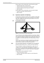
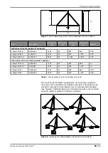
Page 23: ...r allel The reduced current division coefficient kc thus also reduces the calculated separation distance s We recommend installing the cables at least 20 cm apart This keeps the magnetic fields to a m...

Page 24: ...ing electrodes differs by less than a factor of 2 If the earther resistance of individual electrodes deviates by more than a factor of 2 kc 1 should be assumed source DIN EN 62305 3 2011 Table 12 Inst...

Page 25: ...protec tion systems must meet the following requirements and levels of know ledge in potentially explosive areas General principles of explosion protection General principles of protection ratings an...

Page 26: ...OBO Bettermann 26 EN Planning an installation Zone 0 20 Zone 1 21 Zone 2 22 Figure 15 Example of the installation of the isCon ProPlus conductor in the Ex zones of a potentially explosive area...

Page 27: ...ductor guarantees a high degree of protection and can be routed safely under the soft roof Consult the roofer in order to have a waterproof penetration of the insu lated air termination rod created Fa...

Page 28: ...uctor is suitable for routing in the earth It can also be painted e g with the paint of the facade As the external light grey protective jacket is non conductive it must be removed in the contact area...

Page 29: ...e The jacketing of the light grey isCon conductor can be painted It does not possess any electrical properties which could be at risk from paint 5 1 2 Revealing the copper core for connection Using th...

Page 30: ...wo components The components of the coating react automatically on turning in and stick down the grub screws If the screws are released once more the components are separated again and the grub screws...

Page 31: ...the connection element and cable transition are enclosed completely Using a gas torch or hot air at approx 120 C shrink the heat shrinkable sleeve and let it cool 110 130 C 1 2 Figure 25 Shrinking th...

Page 32: ...termination rod with internally routed isCon conductor Legend 1 Air termination rod 2 Internal connection element 3 Isolated central rod 4 Potential connection with potential connection element 5 Ret...

Page 33: ...acketing to a length of 50 mm see also 5 1 Cutting and removing the insulation of the isCon conductor on page 28 Using a stripping stool e g isCon stripper 2 reveal the copper core along a length of 2...

Page 34: ...rub screws Using a fork wrench WAF 19 mm screw the isCon IN connect con nection element onto the isCon conductor until the copper core can be seen completely in the two screw holes 19 mm 25 mm Figure...

Page 35: ...cket maintain a maximum cutting depth of 1 5 mm Measure 1 500 mm from the bottom edge of the isCon IN connect connection element Remove 50 mm of the grey cable jacket with a cable knife jokari knife 5...

Page 36: ...screw 20 Nm 20 Nm Figure 35 Fixing the air termination rod in the air termination rod The internal potential connection element consists of two half shells These must be located in such a way that th...

Page 37: ...the half shells If necessary turn the half shells accordingly Figure 37 Pushing the retaining rod into the central rod Tighten the screws 20 Nm 20 Nm Figure 38 Connecting the insulated air termination...

Page 38: ...ir termination rod with externally routed isCon conductor Legend 1 Air termination rod 2 Connection plate 3 Top connection element 4 Insulated central rod 5 Potential connection with potential connect...

Page 39: ...e isCon connect connection elements on page 30 Only for the light grey isCon conductor To connect the potential connection element the light grey jacket in the contact area must be removed ATTENTION R...

Page 40: ...g torque 24 Nm For two isCon conductors on one air termination rod use the connection plate for two cables type isCon AP2 16 VA Carry out connection in a similar manner to that described here 24 Nm Fi...

Page 41: ...Figure 43 Fastening the potential connection clip to the air termination rod Next steps 5 3 Fastening the air termination rod in the air termination rod stand on page 42 or 5 4 Fastening the air termi...

Page 42: ...it with the lock nut 5 3 2 Erecting the air termination rod stand See also 3 3 Insulated air termination rods on page 12 CAUTION Risk of crushing when erecting the air termination rod stand When erec...

Page 43: ...e lock nuts on the threaded rods Unfold the air termination rod stand Fix the air termination rod stand by screwing in the three locking screws and the spring washers Check that all the screws on the...

Page 44: ...e air termination rod stand Determine the inclination of the air termination rod stand depending on the slope of the roof using a spirit level Compensate for the inclination of the air termination rod...

Page 45: ...ir termination rod with internal isCon conductor Insert the air termination rod into the air termination rod stand from above Figure 49 Inserting the air termination rod in the air termination rod sta...

Page 46: ...d stand from above Tighten the clamp clip thus fixing the air termination rod Figure 51 Fixing the air termination rod in the air termination rod stand In addition fasten the isCon conductor to the ai...

Page 47: ...ith an external isCon conductor Figure 52 Fastening air termination rods to pipes walls or T supports Please note Fasten the air termination rod to the building structure using the sup ports listed in...

Page 48: ...ch a way that it cannot be damaged by sharp edged objects If the isCon conductor is damaged the entire section must be re placed as otherwise the correct function cannot be guaranteed This does not ap...

Page 49: ...stroy devices cause fires and endanger lives If there is a lightning strike the equipotential bonding must not carry light ning current and must be in the protection angle of the lightning protection...

Page 50: ...al connection must be brought into contact with the po tential connection element via the bottom screw and also with the weakly conductive external jacket of the isCon conductor Slacken the bottom scr...

Page 51: ...the air termination rod and the air termination rod stand If you are using an additional conductor to reduce the separation dis tance then observe the following information in order to maintain as ev...

Page 52: ...n terminal 4 in order to prevent surface discharge along the high voltage resistant isCon conductor s x 2 3 1 4 Figure 55 Minimum distance x between the connection element and the equi potential bondi...

Page 53: ...ductor is installed without a potential connection the distance x must be maintained between the con nection element and the last insulated spacer and from this last spacer in the direction of the oth...

Page 54: ...d in contact area 5 6 3 Including the air termination rod stand in the functional equipotential bonding Fasten the crossbar included in the scope of delivery to the air ter mination rod and connect a...

Page 55: ...llations or is run in parallel to them then we recommend additional measures to improve the equipotential bonding To do this connect the isCon conductor multiple times with these instal lations e g ca...

Page 56: ...ntervals 0 5 metres To do this bring the black cable jacket into contact with metallic cable brackets e g isCon H VA or PAE Routing on earthed metallic building structures For routing along an earthed...

Page 57: ...tential bonding of the building Fasten the metallic isCon H VA cable bracket for the isCon conduc tor to it 500 mm isCon H VA Figure 62 isCon conductor in potentially explosive area with isCon H VA ca...

Page 58: ...ion clip 4 is mounted creating the electrical connection between the outer jacket of the isCon conductor and the air termination rod At the end of the isCon conductor the potential is connected with a...

Page 59: ...nation rod stand 4 providing that the potential connection clip 3 is mounted creating the electrical connection between the outer jacket of the isCon conductor and the air termination rod The distance...

Page 60: ...OBO Bettermann 60 EN Mounting variants x 1 2 6 5 3 4 Figure 65 isCon conductor connected to metallic parapet...

Page 61: ...must be mounted in order to create an electrical connection between the jacket of the external isCon conductor and the air termination rod The potential is connected here The internal potential conne...

Page 62: ...able in lightning protection class 1 The potential connection clip 5 type 927 2 6 K must be mounted in order to create an electrical connection between the jacket of the external isCon conductors and...

Page 63: ...ion distance s e g to roof struc tures see Figure 68 No 2 the isCon conductor 1 can be integrated into the mesh providing that the calculated separation distance is less than or equal to the equivalen...

Page 64: ...black semi conductive jacket of the isCon conductor is undamaged An interruption in the external black conductive layer will prevent the cable from functioning In this case replace the isCon conductor...

Page 65: ...he separation distance maintained in the area between the connection element and the first potential connection of the OBO isCon conductor 7 Is the potential connection connected to the local equipote...

Page 66: ...OBO Bettermann 66 EN Own notes...

Page 67: ...System instructions OBO isCon EN 67 Own notes...

Page 68: ...Co KG PO Box 1120 58694 Menden Germany Customer Service Germany Tel 49 0 2371 7899 2000 Fax 49 0 2371 7899 2500 E mail info obo de www obo bettermann com OPTO 170498 Date 01 2018 EN Order No 9131897 B...

Reviews: