background image

Summary of Contents for Ultra LX 2e RTR

Page 1: ......

Page 2: ......

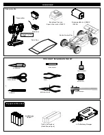
Page 3: ...Cemment Screw Cement CA Screw Cement GEAR GREASE Gear Grease 7 4V Li Po Battery Hard Case x2 pcs L Battery Charger i Po Radio Control Car Servo Brushless Motor 1900KV 30694 Brushless Electric Speed Co...

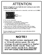
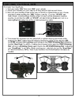
Page 4: ...Then the LED will go to solid Green on both LED 5 Now check your Throttle and Brake by slowly pulling the trigger Make sure you don t free wheel the buggy drive it around slowly 6 Now everything shou...

Page 5: ...5...

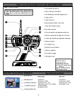
Page 6: ...quency 2 4GHz DC 12V 8 cell AA Type Battery Meas 310 170 75mm Net weight 530g Specification 1 2 3 4 5 6 7 9 11 12 14 15 16 13 8 10 17 17 Battery Cover 7 External Charging Jack Carefully read the instr...

Page 7: ...se use this product according to your local laws and regulations we are not responsible for any incidents or damages 2 4Ghz Binding BIND Binding your RX to Transmitter Turn on the transmitter then tur...

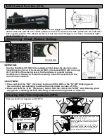
Page 8: ...and sensitivity for the current track conditions ADJUSTMENT INC DEC ST DR 1 Press and hold the INC Increase button until the LED on the ST DR blinking green into a blinking red indicating maximum tur...

Page 9: ...it is at 0 or minimal steering radius 4 To increase the dual rate turn the wheel left or right all the way and hold it while pushing the INC button this will increase the turning radius of the and the...

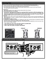
Page 10: ...go now you are at center or neutral position if you go past the RED light it will start flashing GREEN again you are now off center or neutral and going toward the right Racer Tip Always check and be...

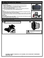
Page 11: ...an be damaged When the transmitter is not used for a long period of time remember to remove the batteries If the batteries do happen to leak clean the batteries case and contacts thoroughly and make s...

Page 12: ......

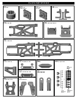
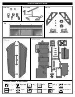
Page 13: ...Plastic Ball End Short 30751 DIFF CASE 30010 FRONT AND REAR GEAR BOX 30751 DIFF CASE FRONT REAR 30761 DIFF CASE CENTER 34063 REAR LOWER ARM 30657 FRONT LOWER ARM 30240 BUMPER 30351 REAR LOWER ARM HOLD...

Page 14: ...INSTRUCTION MANUAL Ensure Free Movement Ensure Free Movement Apply Grease Apply Lubricant Oil Tighten Tighten Do Not Over Tighten Contact Adhesive Contact Adhesive Screw Cement BAG 1 1 Parts Bag Used...

Page 15: ...30776 3x12mm 3x12mm 3x12mm 30110 3mm 30769 30777 30751 30620 30901 Push 3mm tubes into the holes of the diff case 1 3 2 4 Tighten the diff screws in this order Oil Oil 1 3 2 4 Tighten the diff screws...

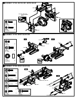
Page 16: ...r w eme C nt Apply Grease Apply Grease 94010 4x12mm Hex Screw x2 94036 5x4mm Set Screw x1 30630 6x13x5mm Ball Bearing x2 5 ASSEMBLY OF THE FRONT GEAR CASE Step 1 Step 2 3x18mm 4x10mm 4x25mm 30010 3065...

Page 17: ...SUSPENSION ARMS Step 1 Step 2 Assemble both right and left side Approx 9 5mm 1 1 4x10mm 2 5mm 2 5mm 36020 36861 36850 36690 30657 36170 36870 4x10mm Set Screw x2 90020 2 5mm E Ring x4 36861 5x35mm Tur...

Page 18: ...p 2 Step 3 36743 36742 36743 36743 30674 36743 30674 8x12x1mm 36741 3mm 30658 3x16mm 30361 30361 30674 30674 30674 x2 94005 3x15mm Hex Screw 94041 3mm Nylon Nut x2 x2 36742 Servo Saver Bushing x4 3674...

Page 19: ...her Alum x4 13 ASSEMBLY OF THE REAR GEAR CASE Step 1 Step 2 30010 30130 30630 30630 30082 5x4mm Apply Grease 94036 5x4mm Set Screw x1 30630 6x13x5mm Ball Bearing x2 Apply Grease Screw ment Ce 14 ASSEM...

Page 20: ...8 3x25mm Cap Screw 94011 4x15mm Hex Screw x2 94036 5x4mm Set Screw x2 x2 94041 3mm Nylon Nut x2 36055 2 5x16 8mm Pin x2 Step 2 Step 1 Builds two rear wheel hubs for use 17 36861 36850 40065 40065 9400...

Page 21: ...SSEMBLY OF THE REAR STABILIZER 94040 3x8x0 8mm Washer x2 94002 3x8mm Hex Screw x2 20 ASSEMBLY OF THE REAR STABILIZER RODS 30403 3x8mm 40199 30341 40199 3x3mm 3x18mm 94006 3x18mm Hex Screw x2 94033 3x3...

Page 22: ...x12mm Flat Head Hex Screw x2 x4 x2 94023 3x25mm Flat Head Hex Screw x2 22 ASSEMBLY OF THE CENTER DIFF ONTO CHASSIS 36100 90mm 4x12mm 4x16mm 94026 4x12mm Flat Head Hex Screw x3 Insert drive shaft into...

Page 23: ...cap joint before assembling center diff 24 Assemble both right and left side 94019 3x10mm Flat Head Hex Screw ASSEMBLY OF THE STONE GUARD x6 41033 3x10mm 4x16mm 4x16mm 3x25mm 36100 86 5mm 94023 3x25m...

Page 24: ...PE INTO BATTERY CASE Step 1 Step 2 30662 30663 94012 4x20mm Hex Screw x1 94027 4x16mm Flat Head Hex Screw x1 94004 3x12mm Hex Screw x2 94042 4mm Nylon Nut x2 4x20mm 3x12mm 4x16mm 4mm 30686 30686 ASSEM...

Page 25: ...E 29 ASSEMBLY OF THE ELECTRIC SPEED CONTROL WIRE INTO RADIO CASE ASSEMBLY OF THE ELECTRIC SPEED CONTRTOL Step 1 Step 2 3x10mm 94002 3x8mm Hex Screw x2 Electronic Speed Control 30693 90AMP ESC 30662 30...

Page 26: ...S ASSEMBLY OF THE STEERING SERVO ONTO RADIO CASE 94040 3x8x0 8mm Washer x4 94003 3x10mm Hex Screw x4 3x10mm 3x8x0 8mm 30662 94019 3x10mm Flat Head Hex Screw x3 94026 4x12mm Flat Head Hex Screw x1 9405...

Page 27: ...rtronics JR SAVOX Futaba HiTech Approx 19mm 30661 30401 30401 3x12mm 30661 38280 3x36mm 3x12mm 30411 30411 30662 94004 3x12mm Hex Screw x2 30411 6mm Ball Socket x2 3x8mm 30662 Step detail Use a screwd...

Page 28: ...ten Tighten the 3x12mm screw temporary EXTREMELY IMPORTANT Insert a piece of notebook paper between spur gear and pinion gear to make correct gear mesh Notebook paper Tighten Tighten PUSH Adjust the m...

Page 29: ...ck rod at top of exposed thread with side cutting needle nosed pliers Be careful not to damage the shock shaft Assemble both left and right sides 40113 P10 O RING x4 41012 3 5mm O Ring x8 REAR SHOCK F...

Page 30: ...l Use tools to tighten as shown be careful not to scratch the shock shaft REAR SHOCK FRONT SHOCK x4 30403 6mm Ball 30403 30403 40643 40643 14mm Step detail 37 5mm 28mm Do Not Over Tighten Do Not Over...

Page 31: ...ENED HALF WAY 50 50 TIGHTENED 100 50 Step 3 Step 1 Step 2 Step 3 TIGHTENED HALF WAY 50 TIGHTENED 100 Step 1 Step 2 Step 3 Cut 7mm 40058 41015 SHORT 41008 41008 41015 LONG Step 1 Step 2 REAR SHOCK FRON...

Page 32: ...is dry glue the other side of the rim Repeat the step and ensure the rim and tire are fully glued Make four tires that are the same Step 1 Step 2 Step 3 Step detail Agglutination place Assemble both l...

Page 33: ...ESC manufacturer to install the wire Body Reamet not included 10806 BLACK 10807 BLUE Step 1 Step 2 Make 7 5mm holes on the body Body Mount as shown Cut the body shelll as shown Make 6mm hole 31143 For...

Page 34: ...DY SHELL p t S ray Pain Mask the windows on the inside with masking tape Paint the body with polycarbonate spray paints When you have finished painting peel off the external protective films When the...

Page 35: ...40528 40527 40520 30656 40527 40550 C C 30403 B B 41010 30655 30102 30658 30380 36740 36742 36740 36742 30361 36741 36850 36790 40038 36700 40039 30689 30082 30010 30130 36850 36020 36861 36690 40199...

Page 36: ...911 30761 30769 30110 30201 30653 30675 E E E E 36100 86 5mm 36100 90mm 30662 30663 30662 30662 30662 30662 30662 30662 37410 40642 30560 30401 30661 38280 3x36mm 30411 30411 30661 30401 41033 30676 3...

Page 37: ...4033 41010 40102 36171 30270 30769 30769 30773 30779 30761 30901 30901 30121 30121 30751 30769 30120 A A B B 86056 80025 B B C C B B D D 30686 41008 41015 40058 40054 41003 40113 30403 41008 41007 410...

Page 38: ...ng the tie rod shorter will make front tires toed out Response will be quicker and may under steer Adjust the length of front steering rod to change the toe angle Making the tie rod longer will make f...

Page 39: ...R 13 16mm 7 95 30661 SERVO HORN HEAVY DUTY BLACK 4 95 40055 SHOCK SHAFTS 3 5m RR 13 16mm 7 95 30662 BATTERY CASE RX BOX LX 1e 19 95 40058 SHOCK BOOTS SILICON 9 95 30663 BATTERY VELCRO STRAPS LX 1e 9 9...

Page 40: ...XLES 4mm ALUM 6PCS 9 95 33991 PCR REAR SHOCK TOWER ULTRA 24 95 33995 PCR STEERING LINK PLATE ULTRA 14 95 33996 PCR UPPER PLATE FRONT DIFF UL 15 95 33997 PCR CENTER DIFF TOP PLATE ULT 15 95 41014 SPRIN...

Page 41: ...e appropriate answers a Yes No Is kit box damaged b Yes No Factory Seal sticker was secure c Yes No I am the original owner d Yes No I have contacted the dealer first 10 Describe your issue fully and...

Page 42: ......

Page 43: ...rovide many hours of enjoyment The registration card should be filled out and mailed to OFNA Racing within 10 days of purchase date IMPORTANT Please print or type filling in the information listed bel...

Page 44: ......

Reviews: