background image


    SERVICE MANUAL 
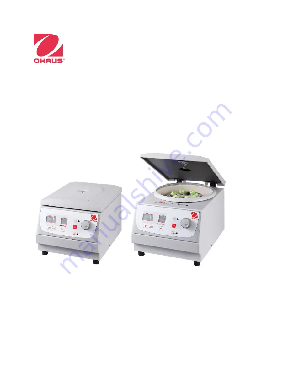
FC5706 CENTRIFUGE 


Ohaus Corporation 7 Campus Drive, Suite 310, Parsippany, NJ 07054, USA +1 973 377 9000 


Summary of Contents for Frontier FC5706

Page 1: ...SERVICE MANUAL FC5706 CENTRIFUGE Ohaus Corporation 7 Campus Drive Suite 310 Parsippany NJ 07054 USA 1 973 377 9000...

Page 2: ......

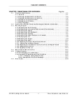
Page 3: ...imes FC5706 1 5 1 7 2 Imbalance Shut Off Data FC5706 1 5 1 7 3 Specifications 1 6 1 8 Service Instructions 1 7 1 8 1 General Technical Descriptions 1 7 1 8 2 Electrical and Electronic Components 1 9 1...

Page 4: ...tiometer 3 5 3 3 3 Replacing the Display 3 6 3 3 4 Replacing the Foil Key Board 3 7 3 3 5 Removing the Housing 3 7 3 3 6 Replacing the Rotor Chamber or Lid Gasket 3 8 3 3 7 Removing the Lid 3 9 3 3 8...

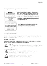
Page 5: ...may lead to personal injury damage to the instrument malfunctions and false results The degree of danger is a part of a safety note and distinguishes the possible results of non observance from each o...

Page 6: ...y other use or intended use is considered improper OHAUS is not liable for damage resulting from improper use 1 3 3 Measures for your protection 1 2 CAUTION Read all safety warnings before installing...

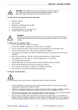
Page 7: ...hould only be performed by authorized personnel 1 3 6 Danger and precautions To protect people and the environment the following precautions should be observed During centrifugation the presences of p...

Page 8: ...e centrifuge while the rotor is still running or rotating with a speed of 2m s 1 4 SERVICE FACILITIES To service a centrifuge the service area should meet the following requirements Area must be clean...

Page 9: ...original packing 1 7 TECHNICAL DATA 1 7 1 Acceleration and Deceleration times FC5706 Acceleration values Deceleration values Rotor number level 0 level 9 level 0 level9 30130880 6x5ml 35 8 25 7 301308...

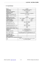
Page 10: ...CHAPTER 1 GETTING STARTED Ohaus Corporation www ohaus com 1 2 FC5706 Centrifuge Service Manual 1 7 3 Specifications 1 6...

Page 11: ...before opening Electrical shock hazards exist within the housing The housing should only be opened by authorized and qualified personnel Do not leave units unsupervised when parts of the housing have...

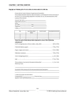
Page 12: ...CHAPTER 1 GETTING STARTED Ohaus Corporation www ohaus com 1 4 FC5706 Centrifuge Service Manual Equipment Redemption Form or Decontamination Certificate 1 8...

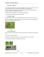
Page 13: ...rical and electronic components 1 8 2 1 Control board The control board consists of one plate The board can only be exchanged completely If there is a defect you have to exchange the complete board Al...

Page 14: ...celerate the rotor only to its permitted rpm Do not use a rotor which isn t set to the control panel 1 8 2 3 Speed signal The actual speed is extracted by a hall effect sensor placed on the lower side...

Page 15: ...tection The imbalance detection is effected by a movement sensor which is placed on the lower side of the motor and is controlling the oscillating motion of the motor The unit stopps when the oscillat...

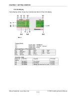
Page 16: ...CHAPTER 1 GETTING STARTED Ohaus Corporation www ohaus com 1 8 FC5706 Centrifuge Service Manual 1 9 LCD Display The following picture shows the individual elements of the LCD display Figure 4 1 12...

Page 17: ...isplay one potentiometer 8 the upper front housing and the foil keyboard These parts can be exchanged separate The potentiometer 1 regulates all parameters which are adjustable by pressing a key and w...

Page 18: ...ch Press the key time 6 and door open 7 hold them and at the same time switch on the unit If the centrifuge is still turned off press simultaneously the keys time 6 and lid 7 and turn on the main swit...

Page 19: ...the special digit service A appears in the display acc dec A 2 see figure 9 Figure 2 In the display rpm rcf A 1 the number of motor starts is indicated now 2 1 3 Submenu Duty Cycle Here you can read...

Page 20: ...until the special digit service h appears in the display acc dec A 2 Figure 4 In the display rpm rcf A 1 the running time of the motor is indicated now 2 1 5 Submenu software status Here you can read...

Page 21: ...the special digit service E appears in the display acc dec A 2 Figure 6 By pressing the key rpm rcf 4 the display rpm rcf A 1 is activated and you can scroll through the error list with the potentiome...

Page 22: ...ttom to the top line in the display rpm rcf A 1 The key accel decel 5 excluded 2 1 8 Subemenu Activation Deactivation of the imbalance sensor Activate the operation menu as described in chapter 9 3 1...

Page 23: ...ice Menu Part 2 To get access to the second level of the service menu you have to press the key stop 3 for longer than one second Now you are asked for a code in the display rpm rcf A 2 adjust the cod...

Page 24: ...With this settled value the unit should run through Through the transport or the setup of the unit it may occur that this value will react unlike In case the unit does already cut off at the adjusted...

Page 25: ...ou can choose the respective setup between 30 and 20 with the potentiometer 8 Note After all points have been reviewed and or set up you have to press shortly the key start to store all parameters Oth...

Page 26: ...line solutions e g salt water phenol halogenated hydrocarbons Cleaning units rotors accessories Turn the device off and disconnect it from the power supply before you begin any cleaning or disinfectin...

Page 27: ...the power cord with a damp cloth 6 Wash the rubber seals and rotor chamber thoroughly with water 7 Rub the dry rubber seals with glycerol or talc to prevent these to becoming brittle Other components...

Page 28: ...s to plastic materials at ambient temperatures But at the high temperatures of the autoclaving those residues may corrode and destroy the plastic The objects must be thoroughly washed up with distille...

Page 29: ...tremely pollute the rotor chamber the rotor the buckets and the samples If necessary replace the adapters tubes and accessories to avoid further damages Check the rotor bores regulary for residues and...

Page 30: ...ring by putting a screw driver into the 2 notches and then lever the front part out Pull the lower edge of the covering away from the mounting plate of the housing Pull the covering out of the upper g...

Page 31: ...ll electrical contacts to the shaft encoder on the back side of the front housing Figure 3 3 3 3 Replacing the display Loosen all electrical contacts to the display on the back of the front housing Re...

Page 32: ...the foil matches precisely and the window of the foil keyboard lies exactly over the display Reassemble the control panel in reversed order and mount it back in the front housing 3 3 5 Removing the ho...

Page 33: ...the fixing ends are at the back part of the chamber see figure 27 Start the mounting always with this glued ends When mounting the rotor chamber make sure that the ventilation drilling behind on the...

Page 34: ...8 Replacing the hinges Remove the lid as described in chapter 3 3 7 Lay the lid with the upper side down on a smooth under packing to avoid any scratches Loosen the screws of the respective hinges on...

Page 35: ...ve the connection cable to the motor on the control board a current supply of the motor b speed and imbalance sensor Figure 9 Turn the motor fixing screws out of the rear side of the ground plate Lift...

Page 36: ...ings screws and take the control board out Figure 10 Put in the new control board connect all electrical contacts and re assemble the unit in reverse order 3 3 11 Checkup the imbalance sensor Movement...

Page 37: ...carefully Attention Risk of breakage Replace the board Glue the speed magnet with super glue again in the right position and re assemble the unit in reverse order 3 2 13 Replacing the lid lock Remove...

Page 38: ...onto the centrifuges seal Afterwards tighten the screws of the hinges under a slight pressure onto the lid 2 Put some washers underneath of the lid lock in that way that the lid latch is centric to t...

Page 39: ...nected housing and bottom housing Centrifuge grounding Switch power connection and Rectifier Bridge connection A Grounding from Top Housing B Grounding from Motor C Grounding from Connector Power A Sw...

Page 40: ...on Main PCBA connection Lid Lock connection A A1 Brown to Main PCBA point X21 1 A2 Blue to Main PCBA point X21 3 B B1 Brown to Main PCBA point X21 4 B2 Blue to Main PCBA point X21 6 A Black Red from M...

Page 41: ......

Page 42: ...Many thanks in advance for your support 3 5 2 Possible error messages and their solutions 3 5 2 1 Lid release during power failure In case of power failure or malfunction the lid of the centrifuge can...

Page 43: ...m 3 13 FC5706 Centrifuge Service Manual Figure 12 3 5 2 2 1 Description of the error message system The error message is shown in the time display through particular numbers At the same time the word...

Page 44: ...quency converter control unit is defective 11 Temperature sensor is defective Temperature sensor is defective cable break plug is loose between control units to frequency converter control unit is def...

Page 45: ...trifuge Service Manual Error No Description Cause 55 Over speed Transmission error firmware error frequency converter us defective 60 Intermediate circuit under voltage Motor defective control board d...

Page 46: ......

Page 47: ...014 Ohaus Corporation all rights reserved Registered trademark of Ohaus Corporation The information contained in this manual is believed to be accurate at the time of publication but Ohaus Corporation...

Reviews: