background image

Oki  Data  CONFIDENTIAL

       
 C3200n/C5150n/C5200n
     C5400n/C5510MFP 


Service Manual


060125A

Summary of Contents for C3200n

Page 1: ...Oki Data CONFIDENTIAL C3200n C5150n C5200n C5400n C5510MFP Service Manual 060125A...

Page 2: ...42615101TH Rev 8 2 Oki Data CONFIDENTIAL...

Page 3: ...without prior notice Inpreparingthedocument effortshavebeenmadetoensurethattheinformationinitisaccurate However errors may be crept into the document Oki Data assumes no responsibility for any damage...

Page 4: ...ace Signals 24 2 OPERATION DESCRIPTION 25 2 1 Electrophotographic Process Mechanism 25 2 2 Printing Processes 30 3 PRINTER INSTALLATION 40 3 1 Precautions and Prohibition 40 3 2 Printer Unpacking Proc...

Page 5: ...40 5 4 2 4 Motor and clutch test 143 5 4 2 5 Test printing 145 5 4 2 6 Color registration adjustment test 150 5 4 2 7 Print density adjustment test 150 5 4 2 8 Consumable counter display 151 5 4 2 9 C...

Page 6: ...120 127 051 219 7 5 2 12 Print Speed is Slow Low Performance 220 7 5 2 13 Option unit is not recognized 220 7 5 2 14 LED head is not recognized Error 131 132 133 134 221 7 5 2 15 Toner cartridge is no...

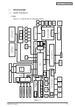
Page 7: ...Fuse Cut Out Exit Motor Control Color Registration Density Thermistor Signals Environment Temperature Humidity Signals 28MHz FLASH 8M bit SRAM 256Kbit High Voltage Interface Fan Control Cover Open Fa...

Page 8: ...HOP 1st P E Sensor Belt Unit PU Board Driver Relay Board Fuser Inlet EXIT Sensor Density Sensor Color Registration Board Right Color Registration Board Left M BELT M HEAT Belt Unit Fuse Cut Out Fuser...

Page 9: ...d M BELT M HEAT Belt Unit Fuse Cut Out Fuser Fuse Cut Out Up Low Thermistor Fuse Cut Out Exit Motor Control Color Registration Density Thermistor Signals Heater flame thermistor Environment Temperatur...

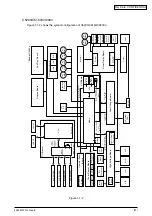
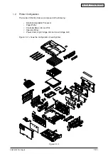
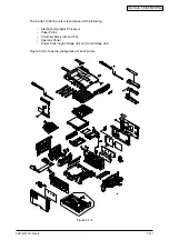
Page 10: ...tion The inside of C5400 printers is composed of the following Electrophotographic Processor Paper Paths Controller Block CU and PU Operator Panel Power Units High Voltage Unit and Low Voltage Unit Fi...

Page 11: ...42615101TH Rev 8 11 Oki Data CONFIDENTIAL...

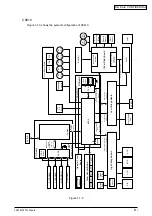
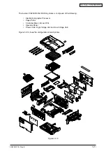
Page 12: ...5200 C5150 C3200n printers is composed of the following Electrophotographic Processor Paper Paths Controller Block CU and PU Operator Panel Power Units High Voltage Unit and Low Voltage Unit Figure 1...

Page 13: ...42615101TH Rev 8 13 Oki Data CONFIDENTIAL...

Page 14: ...de of C5510 printers is composed of the following Electrophotographic Processor Paper Paths Controller Block CU and PU Operator Panel Power Units High Voltage Unit and Low Voltage Unit Figure 1 2 5 sh...

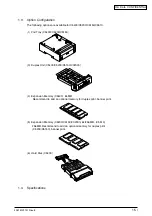
Page 15: ...d Tray C5400 C5200 C5150 3 Duplex Unit C5400 C5200 C5150 C3200n 4 Expansion Memory C5400 64 MB Recommend to add an optional memory for duplex print banner print 5 Expansion Memory C5200 C5150 C3200n 6...

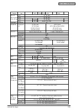
Page 16: ...ing lightness 110 127VAC Range 99 140VAC 220 240VAC Range 198 264VAC 950W 420W 12PPM Color 20PPM Mono 6PPM OHP Color 12PPM OHP Mono 9sec K 14sec Color A4 13 6 345mm approx 55lbs 25kg 14 355mm 26 4kg T...

Page 17: ...14 Letter Exective A4 A5 B5 Multi Purpose Tray Legal13 Legal13 5 Legal14 Letter Exective A4 A5 B5 A6 C5 DL Com 9 Com 10 Monarch CustomSize Banner upto 1200mm If the length exceeds 356 the width has t...

Page 18: ...3 Typeface Rasterizer Barcode OCR Japanese PCL Fonts Japanese PS Fonts N A 20 53lb 75 203gsm OHP Available Over sea 20 28lb 75 105gsm 17 47lb 64 176gsm 17 32lb 64 120gsm Available N A Available Y M C...

Page 19: ...0 C5510 C5200n ne C5200n C5200n C5400n C5400n C5400n C5150n C3200n C3200n C3200n C5400 64 256 MB N A No 2nd tray available N A Not available 2nd tray mecha Legal Univ 530 Available N A 64 128 256 MB N...

Page 20: ...el Interface 1 5 1 2 Parallel Interface Connector and Cable 1 Connector Printer side 36 pin receptacle Type 57LE 40360 12 D56 made by Daiichi Denshi or equivalent Cable side 36 pin plug Type 57FE 3036...

Page 21: ...USY 0 5 s min 0 5 s min 0 5 s min 0 5 s max 0 5 s min 0 min 0 min 0 5 s to 3 s 0 min ON LINE SW BUSY 100 ms max SELECT SELECT ACKNOWLEDGE ON LINE SW BUSY INPUT PRIME SELECT ACKNOWLEDGE BUSY 50 s min M...

Page 22: ...R HIGH without exception when the parallel interface is enabled 14 NAutoFd HostBusy PR Used in bidirectional communication 15 Unassigned 16 GND Signal ground 17 FG Chassis ground 18 5V PR Used for sup...

Page 23: ...ontrol Self power device 1 5 2 2 USB Interface Connector and Cable 1 Connector Printer side Type B receptacle Upstrem port DUSB BRA42 T11 D2 made by DDK or equivalent Connector pin layout 2 3 4 1 Cabl...

Page 24: ...ion layer LPR FTP TELNET HTTP BOOTP SMTP 1 5 3 2 Network Interface Connector and Cable 1 Connector 100 BASE TX 10 BASE T Connector pin layout 2 Cable RJ 45 UTP cable with connector Category 5 recommen...

Page 25: ...eated on the surface based on electrical potentials on the surface 3 Development Charged toner is attracted to the latent image of the drum by static electricity and makes the image visible on the sur...

Page 26: ...e a static latent image being created on the surface Power Supply Unit OPC Drum Paper OPC Drum LED Head CH Roller LED Head 4 Development Toner is attracted to the latent image on the surface of the dr...

Page 27: ...m the back Applying high voltage provided by a power supply to the roller transfers the roller induced charge to the surface of the paper at the contact between the roller and the paper attracting the...

Page 28: ...ety thermostat is provided and when the temperature of the heat roller rises to or exceeds a predetermined temperature it opens cutting off voltage supply to the heater Thermostat Thermistor Thermisto...

Page 29: ...d collected in the waste toner area of a toner cartridge Toner Cartridge Drum Cleaning Blade Image Drum ID Unit Waste Toner Area 8 Transfer Belt Cleaning Residual toner on a transfer belt is scraped o...

Page 30: ...ng are operations in two side duplex printing In duplex printing paper passed through a fuser unit after it is first printed on the back is fed into a duplex unit via a dup in separator Reversing roll...

Page 31: ...Solenoid ON Solenoid Lever Solenoid OFF Hopping Gear Assy IN2 Sensor IN2 Sensor IN1 Sensor IN1 Sensor Figure 2 1 Figure 2 2 2 Paper Feed from MPT 1 As indicated in Figure 2 3 when the solenoid is OFF...

Page 32: ...t sits with one carrier roller immediately below each color s drum and the carrier belt between them By the application of a fixed voltage the carrier belt and carrier roller feed paper on the carrier...

Page 33: ...ns during monochrome printing When the C ID motor rotates CW the lift uplink slides to the right and as indicated in Figure 2 7 all units other than the K ID moves UP The printer is now ready for blac...

Page 34: ...Fuser Motor CCW Eject Roller Drive Heat Roller Drive Fuser Unit Figure 2 8 Figure 2 9 6 Operations when the Color Drift Sensor and Density Sensor Cover is Opened 1 As indicated in Figure 2 9 when the...

Page 35: ...fter the previous implementation Toner amounts on the produced patterns contamination of the sensor with toner problems with opening or closing of the sensor shutter or other reasons a color misalignm...

Page 36: ...g closing motion of the sensor shutter is normal with MOTOR CLUTCH TEST of the self diagnostic mode Exchange the shutter unit when the opening closing motion is not complete BELT REFLX ERR Check 4 Che...

Page 37: ...s almost new in power on When ID count value is over 500 from the previous implementation Toner amounts on produced patterns contamination of optical sensors with toner problems with opening or closin...

Page 38: ...mal state if the connection state is wrong Check 2 Check that the surface of the sensor is clean without paper dust and toner Wipe it off if it is dirty EDENS SHUTTER ERR Check 3 Check whether an open...

Page 39: ...veloped to binary data which is printable Dot counter counts the data as print dots in LSI Calculate the amount of the used toner with this count value to display a remaining amount Meanwhile the tone...

Page 40: ...with liquids such as water on the printer Doing so may cause an electric shock and or fire leading to personal injury Do not touch the fuser and other parts when opened the cover Doing so may result i...

Page 41: ...a monitor or television Please lift both sides when moving the printer Since this printer has about 25kg of weight please raise by two or more persons Do not come closer to the paper s exit area when...

Page 42: ...npacking Procedure Punch four handle holes each on the side or the end of the carton box as shown below to lift it Except C5510 Handle Holes each on side or on end Each printer weighs about 25 kg Lift...

Page 43: ...42615101TH Rev 8 43 Oki Data CONFIDENTIAL C5510 Handle Holes each on side or on end...

Page 44: ...32 C Ambient Humidity 20 to 80 relative humidity Maximum Wet Bulb Temperature 25 C Take care not to allow dew condensation on printers When installing printers in an area of which ambient humidity is...

Page 45: ...printer weighs about 25 kg Lift it by more than one person Personal injuries may occur Printer main body Image Drum Cartridges with Starter Toner Cartridges four sets contained in printer Explain tha...

Page 46: ...pe C5510 2 Remove the paper cassette 3 Pull out the retainer frontward OPEN button Retainer 4 Press the OPEN button to open the top cover 5 Pulling down the lever blue of the fuser unit in the directi...

Page 47: ...f about 1500 lux or more or for five minutes or more room light Make sure that a blue lever of the toner cartridge should not be moved here Toner Cartridge Image Drum Cartridge 2 Put an image cartridg...

Page 48: ...ble with Starter toner a toner cartridge which is attached at the time of purchase under the condition of A4 and 5 print density Make sure that a lever of the toner cartridge turn in the arrow directi...

Page 49: ...ciently loosen the paper and jog the paper so as that its edges line up 4 Load the paper face down in the paper cassette Note Print paper must be placed in the paper cassette so as to touch sides of t...

Page 50: ...ay 2 Align the manual feeding paper guide with the size of print paper 3 Jog the paper so as that its edges line up Manual Feeding Paper Guide Manual Feeding Paper Guide MP Tray Paper Supporter 4 Inse...

Page 51: ...hem Do not tie in bundles or knot power supply cords in use for printers Do not use damaged power supply cords for printers Do not use star burst connections for printers Do not connect a printer to t...

Page 52: ...ing wire is connected to the grounding terminal Insert the power supply cord into the receptacle socket O I Grounding Wire Grounding Terminal Press ON I of Power Switch O I The control panel provides...

Page 53: ...own below without turning off the printer immediately Note The internal hard disk may be damaged and unusable if the printer is switched off immediately SHUTDOWN MENU is displayed only when an optiona...

Page 54: ...Note Be sure to use Oki Data genuine memory Printers do not operate using memory other than Oki Data genuine memory Installing 64 MB extension memory in printers is recommended for the printers to pr...

Page 55: ...ver Screw 5510 Install Memory C5400 1 Remove static electricity by bringing a bag into contact with a metal part before the memory is taken out of the bag 2 Insert the memory into an empty slot 3 Make...

Page 56: ...the memory is held completely by the top and bottom lock lever Note Do not touch electronic components and connector terminals Be careful of the memory direction There is a cutting part to adapt to th...

Page 57: ...rd on the printer Type MLTRY C4C1 Type Power Off Printer to Remove Power Supply Cord Note Installing the second tray with the printer powered on may cause a problem with the printer O I Place Printer...

Page 58: ...XU C4C Power Printer Off to Remove Power Supply Cord Note nstalling the duplex unit with the printer powered on may cause a problem with the printer O I Remove Protective Tape from Duplex Unit Protect...

Page 59: ...to download a font Note Turn off the power after Shut down menu is executed when an internal hard disk is installed The hard disk may be damaged and unusable if the printer is switched off immediatel...

Page 60: ...er 1 Press OPEN button to open the top cover Top cover OPEN button Handle Front cover 2 Lift up the handle in the center of the front cover and then pull the front cover Front cover Note It differs fr...

Page 61: ...cover is not detached Multi purpose tray Front cover The condition where the front cover is open The condition where Multi purpose tray is open Install an internal hard disk 1 Pull a lock lever of the...

Page 62: ...is appropriately installed 1 Print MenuMap Refer to Chapter 3 6 Menu Map Printing to print MenuMap 2 Check the capacity of the internal hard disk is displayed in HDD Memo The capacity of the hard dis...

Page 63: ...on Contained in MenuMap Check the total memory size appearing at Total Memory Size on the header of MenuMap 2 Checking for Proper Second Tray Recognition Checking for Proper Second Tray Recognition Ch...

Page 64: ...C3200n 1 Set A4 papers in a tray 2 Press the MENU switch a couple times to show Information menu 3 Press the ENTER switch to show Menu map Printing EXECUTE 4 Press the ENTER switch Menu map printing...

Page 65: ...42615101TH Rev 8 65 Oki Data CONFIDENTIAL Sample In case of C5200 C5150 C3200n...

Page 66: ...6 Oki Data CONFIDENTIAL In case of C5510 1 Set A4 papers in a tray 2 Press the ONLINE switch for 2 seconds and release ONLINE LED Green blinks on and off and Menu map printing is started Only one page...

Page 67: ...Computer Memo The USB cable can be plugged in and off with the printer powered on For the purpose of printer driver and USB driver installation to be performed later power off the printer Connect Per...

Page 68: ...hernet cable in the network interface connector of the printer 3 Plug the cable in the hub Network Interface Connector Parallel Connection Prepare a Parallel Port Cable and Power Off Printer and Perso...

Page 69: ...vy Label paper 1 Label paper 2 Transparency film Light Label paper Transparency film Setting values of the operation panel Light Medium Heavy Ultra heavy Thicker paper Thickest paper Regular paper 3 P...

Page 70: ...for replacing the parts assemblies and units in the field The replacing procedure is given for detachment To attach use the reverse procedure The Parts No 1 2 etc appearing in this manual vary from th...

Page 71: ...circuit boards and the units Table 4 1 1 Maintenance Tools No Q ty Place of use Remarks Service Tools 1 2 3 4 5 6 8 No 2 200 Philips screwdriver Magnetized No 3 100 screwdriver No 5 200 screwdriver Di...

Page 72: ...ibes the procedures for replacing the parts and assemblies shown in the following disassembly chart 4 2 1 Left Side Cover Except C5510 1 Open the top cover 1 2 Open the feeder unit 2 3 Remove the scre...

Page 73: ...cover L 3 Tool No 2 4 Remove the E ring 4 Tool No 2 5 Remove the shaft 5 6 Remove the Guide Damper L 6 and Spring 7 7 Remove the screw golden 8 and then the plate lower L 9 8 Remove the screw golden 0...

Page 74: ...4 Oki Data CONFIDENTIAL 4 3 1 2 loosen 4 2 2 Right Side Cover Except C5510 1 Open the top cover 1 2 Open the feeder unit 2 3 Loosen the screw 3 to detach the right side cover 4 Tool No 1 Figure 4 2 2...

Page 75: ...15101TH Rev 8 75 Oki Data CONFIDENTIAL 4 3 1 2 loosen Figure 4 2 2 2 Right Side Cover C5510 1 Open the top cover 1 2 Open the feeder unit 2 3 Loosen the screw 3 to detach the right side cover 4 Tool N...

Page 76: ...101TH Rev 8 76 Oki Data CONFIDENTIAL 1 4 2 3 Face Up Tray 1 Open the face up tray 1 in the direction of the arrow and disengage it at its two places to detach it with bowing down Figure 4 2 3 Face Up...

Page 77: ...golden 1 Tool No 1 3 As shown in Fig 2 insert a flat blade driver Tool No 3 into the hole A to disengage the claw A at each of the two places 4 Disengage the two claws B and pull in an arc the rear co...

Page 78: ...ssy LED Assy Springs 1 Open the top cover 1 2 As shown in Fig 2 push in the direction of the allow after removing a cable Then disengage the hook A first and the hook B to detach LED Assy 2 the two sp...

Page 79: ...5400 1 Remove the Print Engine Controller PCB see section 4 2 7 2 Remove the screw 1 and then the head cable 2 Tool No 1 3 Remove the eight screws golden 3 then detach the controller PCB 4 SPA 4 PCB T...

Page 80: ...42615101TH Rev 8 80 Oki Data CONFIDENTIAL 1 2 3 4 5...

Page 81: ...cable 4 Tool No 1 5 Remove the six screws golden 5 and the cable 6 then detach the controller PCB 7 Tool No 1 C3100 ARC 2 or SPY 2 PCB C5200 ARC 3 or SPY 3 PCB C5150 ARC 4 or SPY 4 PCB C3200 SPY 5 PC...

Page 82: ...4 and then the Lower Assy R 5 and spring 6 7 Remove the spacer lower R 7 8 Unscrew the three screws golden 8 disengage the claws A and remove the plate shield assy GDI 9 Tool No 1 9 Remove the screw g...

Page 83: ...1 Open the top cover 2 Remove the right side cover see section 4 2 2 3 Remove the connector 1 and disengage the two hooks A of to detach the FAN CU 2 4 Remove the three screws golden 3 disengage the...

Page 84: ...42615101TH Rev 8 84 Oki Data CONFIDENTIAL 1 2 3 4 5 6 7 8 9 0 A B C...

Page 85: ...FSNS SSNS PE OPE Print engine controller PCB C5200 C5150 C3200n 1 Remove the plate shield Assy GDI see section 4 2 6 steps 1 to 3 2 Remove the three screws golden 1 and all the connectors to detach t...

Page 86: ...ion 4 2 6 steps 1 to 3 2 Remove the three screws golden 1 and all the connectors to detach the print engine controller PCB 2 Tool No 1 Figure 4 2 7 4 Print Engine Controller PCB C5510 2 1 1 2 POWER DR...

Page 87: ...LT PRT PCB SSNS connector PRP PCB PRO PCB CN connector Print Engine Controller PCB PRN PCB RSF PCB CN connector Low voltage power supply PCB CN4 connector Driver relay board PCB PUIF connector Driver...

Page 88: ...emove the right side cover see section 4 2 2 3 Remove the rear side cover see section 4 2 4 4 Remove the plate shield Assy GDI see section 4 2 6 step 2 5 Remove the LED head cable 6 Remove the two E s...

Page 89: ...ction 4 2 4 4 Remove the plate shield Assy GDI see section 4 2 6 step 2 5 Remove the LED head cable 6 Remove the two screws black 1 to remove the stay Assy R 2 7 Remove the two screws black 3 to remov...

Page 90: ...2 3 1 4 2 9 Top Cover Except C5510 1 Open the top cover assy 2 Remove the ten screws black 1 to remove the guide paper eject 2 Tool No 1 3 Remove the ten screws black 3 to detach the cable cover 4 and...

Page 91: ...L C5510 1 Open the top cover assy 2 Remove the ten screws black 1 to remove the guide paper eject 2 Tool No 1 3 Remove the ten screws black 3 to detach the cable cover 4 and the top cover 5 Tool No 1...

Page 92: ...unit 3 Remove the right side cover see section 4 2 3 4 Remove the plate shield Assy see section 4 2 7 step 2 5 Make Control Panel Assy connector removal 6 Remove the four screws golden 1 then detach t...

Page 93: ...the two claws B of the Cover Assy OP 4 with inserting a flat blade driver Tool No 3 to remove the Cover Assy OP 4 and the sprint torsions 5 4 As shown in Fig 3 inserting a flat blade driver Tool No 3...

Page 94: ...nector to detach the fuser motor A Tool No 1 Note When reassembling the ID FAN 4 Low voltage Power Unit FAN 7 check the attachment direction When reassembling the Low voltage Power Unit6 check the set...

Page 95: ...4 2 12 4 Remove the four screws golden 1 and the two E snaps 2 to remove the plate outer 3 Tool No 1 No 8 5 Remove the gear idle ID K 4 Y and C 5 each in one piece and M 6 and the spring 7 of the sole...

Page 96: ...the Plate Heat 2 Tool No 1 4 Remove the two Spring Torsions 3 and disengage the four claws to remove the cover driver 4 with a flat blade driver Tool No 3 5 Make screw golden 5 and connector removal...

Page 97: ...istor Flame thermistor Density sensor Color registration sensor Heater AC Heater moter Board PRM POW DENS RCR FUSER LCR HEAT PUIF EXIT BELT PRN PCB DRPOW connector Driver Relay PCB PRM PCB Right color...

Page 98: ...e connector and detach the FAN Fuser 4 turning it clockwise 5 Remove the connector and claws to detach the cover open switch 5 6 Remove the screws golden 6 and black 7 seven claws and connector to rem...

Page 99: ...Open the MPT Assy 1 2 Remove the two stoppers with opening the two arms of MPT Assy 1 out and remove the two supports to detach MPT Assy 1 pulling the two supports in the direction of the allow Figure...

Page 100: ...emoval to detach the Board RSF 5 7 Remove the lever 6 by turning it until it is unlocked Tool No 1 8 Remove the two screws black 7 to remove the stay L 1 Tool No 1 9 Remove the four screws black 8 dis...

Page 101: ...e Fan fuser see section 4 2 15 8 Remove the E snap 4 Disengage the latch to remove the gear assy planet 5 the shaft 6 and the three rollers 7 9 Unscrew the two screws golden 8 to remove the side plate...

Page 102: ...CONFIDENTIAL C ID motor Position the motor and the connector to the arrows M ID motor Y ID motor K ID motor 1 2 9 8 8 0 A C D B E F G 6 5 4 7 H I J K L M R S 3 O N P U Q 1 T 4 4 Figure 4 2 18 Main Mot...

Page 103: ...42615101TH Rev 8 103 Oki Data CONFIDENTIAL 1 Latch 4 2 19 Feed Roller 1 Remove the cassette 2 Unlatch and detach the feed roller 1 Figure 4 2 19 Feed Roller...

Page 104: ...Remove the two claws to separate the Guide Eject Lower 2 and the Guide Eject Upper 3 3 Remove the Gear Idle Eject 4 and Stopper Shaft 5 then detach the Shaft Assy Eject FU 6 and the Shaft Assy Eject...

Page 105: ...105 Oki Data CONFIDENTIAL Blue 1 3 2 4 2 21 Fuser Unit 1 Open the top cover 1 2 Rise the Fuser Unit Lock Levers two blue portions 2 in the directions of the arrows to detach the fuser unit 3 Figure 4...

Page 106: ...Blue Blue 1 5 3 3 4 2 4 2 22 Belt Unit 1 Open the top cover 1 2 Remove the image drum unit 3 Turn the lock levers two blue portions 2 in the direction of the arrow and grasping the lever blue 3 detac...

Page 107: ...e in removing or installing However specified lubrication oil has to be used to lubricate if oil is wiped off Inbrication work 1 Mark and name of the Iubrication oil EM 30L Molycoat EM 30L HP 300 Moly...

Page 108: ...Hopping End surface EM 30L Class C Gear bottom surface EM 30L Class C The side of groove EM 30L Class C Cog surface abnd end surface EM 30L Class C Ratch portion Hatching portion EM 30L Class C Post...

Page 109: ...701 Guide Assy Cassette L EM 30L Class C Guide Casette L Apply a normal amount of Molycoat EM 30L to the hatched portions 3 42050101 Guide Assy Cassette R EM 30L Class C Guide Casette R Apply a normal...

Page 110: ...42057301 Gear Assy HP EM 30L Class C Holder Gear A Apply a normal amount of Molycoat EM 30L to the hatched areas 5 1 42053501 Plate Ass Side R EM 30L Class C Bracket Inner Caulking Apply a normal amo...

Page 111: ...pply a normal amount of Molycoat EM 30L to the hatched areas EM 30L Class C Apply a normal amount of Molycoat EM 30L to the hatched areas EM 30L Class A Enlarged figure Apply a small amount of Molycoa...

Page 112: ...tched areas EM 30L Class A Apply a small amount of Molycoat EM 30L to the hatched areas EM 30L Class A Apply a small amount of Molycoat EM 30L to the hatched areas EM 30L Class C Apply a normal amount...

Page 113: ...Molycoat EM 30L to the hatched areas 9 42087001 Cassette Assy Frame Separation Assy Fulcrum of rotation and side Class C The application of grease protruding over on the paper carriage surface is not...

Page 114: ...the surface of gear teeth shaft and the flange portions 8 places No Molycoat at the paper running face EM 30L Class C Grease is not applied to this hatching portion Apply a normal amount of Molycoat E...

Page 115: ...oat EM 30L to the hatched areas B 42464901 Frame Assy Base Cassette Assy PM Class C Apply PM to the hatched portion in a small quantity 1 The application mathod wipe with the cloth with which PM sank...

Page 116: ...river PU Caulking Gear Idle Belt EM 30L Class C Apply a normal amount of Molycoat EM 30L 4 portions EM 30L Class C Apply a normal amount of Molycoat EM 30L EM 30L Class C Apply a normal amount of Moly...

Page 117: ...ter Unit PX724 Plate Ass Side R Spring Torsion L Spring Torsion R EM 30L Class C Apply a normal amount of Molycoat EM 30L to the hatched areas 2 places At both Sides PM is applied to the portion of th...

Page 118: ...42615101TH Rev 8 118 Oki Data CONFIDENTIAL C 3 42621701 Printer Unit PX724 Grease is not applied to a metal shaft Gear Idle Heat EM 30L Class C Apply a normal amount of Molycoat EM 30L...

Page 119: ...42615101TH Rev 8 119 Oki Data CONFIDENTIAL C 4 42621701PA Printer Unit PX724 For C5510 Only Apply a normal amount of Panmotoroil PM Class C...

Page 120: ...626501 Sensor Assy Color Regist Plate Sensor C Regist Cover Sensor C Regist Apply a small amount of Molycoat ME 30L to the hatching areas 4 places Molycoat shall not adhere to the surface of Cover Sen...

Page 121: ...L E 42076601 Roller Assy Idle FD 1 2 Method of amount of grease Before 1 assemble at 2 apply small amount of Molycoat EM 30L to the sliding portions hatching portion of 1 and 2 Class S Exploded View N...

Page 122: ...eft Side No 01 No 02 No 03 No 02 Reft Side No 03 Center Side Method of amount of grease After 2 or 4 assemble at 3 or 5 apply small amount of Molycoat EM 30L to the sliding portions hatching portion o...

Page 123: ...42615101TH Rev 8 123 Oki Data CONFIDENTIAL G 43016101 Lower Assy R For C5510 Only EM 30L Class C Apply a normal amount of Molycoat EM 30L Gear Z20...

Page 124: ...nabled after rebooting TYPE2 is the default for OEL APS OEMA TYPE1 is the default for the other distribution channel Selecting by the ENTER key then pressing the On line switch will prompt initializat...

Page 125: ...disabled in this menu will not be displayed on User Menu s or Admin Menu s PERSONALITY When print data in the PDL language set to DISABLE is received the printer will display INVALID DATA and discard...

Page 126: ...is effective in ESC P Emulation Specifies the function of AUTO FEED XT signal When ENABLE is selected if AUTO FEED XT signal is low level in power on sequence Line feed for CR code is performed When D...

Page 127: ...Rev 5 or later Japanese version 42678801FU02 Rev 5 or later English version 2 Program of the maintenance utility is as below It is possible to download a program of the maintenance utility Person in c...

Page 128: ...board Copying LED head correction data 1 Adjustment Purpose Copy the above data to another board when it is necessary to replace to another PU board due to maintenance replacement Reprogramming print...

Page 129: ...2 4 2 2 7 3 Section 2 4 1 2 6 Section 2 4 1 3 1 Section 2 4 1 3 2 Section 2 4 1 3 3 Section 2 4 1 3 4 Section 2 4 1 4 1 Copying the consumable counter Drum counter Y M C K Fuser counter Belt counter T...

Page 130: ...or Registration Test 2 Density Adjustment Test 2 Setting of Auto Density Adjustment Controller Parameter 2 Prohibited to use NVM Initialization 2 Prohibited to use Counter Display 2 Local Parameter Se...

Page 131: ...Press MENU and or MENU repeatedly until you see the language you wish to select 6 Press ENTER to select this language 7 Press ON LINE to exit the menu and return the printer to standby The LCD displa...

Page 132: ...s print nonuniformity due to temperature variation With faded images change the value With scattering or snowing images in print output of high print density decrement the value With faded images in p...

Page 133: ...IAL 5 4 2 Self diagnostic Mode Explanation for each LEVEL 0 and LEVEL 1 5 4 2 1 Operator panel Operating descriptions on self diagnosis are premised on the following operator panel layout For ODA For...

Page 134: ...CHIP DISPERSION ADJUST DENS ADJ TEST 2 NV RAM INITIAL CONSUMABLE STATUS PRINTER STATUS LOCAL PARAMETER SET ENGINE PARAMETER SET 2 WASTE TONER CNT LED HEAD DATA 1 Displaying Next or Previous Menu Items...

Page 135: ...nt by showing the engine status 3 It is possible to confirm temperature control of the electric heater is conducted with a status of OFF ON 4 It enables to confirm whether detected temperature and hum...

Page 136: ...UTE DENS ADJ PAR SET DENS ADJ RESULT AUTO CALIBRATION NV RAM INITIAL MENU MENU CONSUMABLE STATUS FUSER UNIT TR BELT UNIT K ID UNIT Y ID UNIT M ID UNIT C ID UNIT K TONER Y TONER M TONER C TONER M WASTE...

Page 137: ...t Testing Setting of Auto color density adjustment control parameter NVM Initialization Prohibited to use Display of Consumable Counter Display of Record Counter of All Consumables Item Checking input...

Page 138: ...ngine Parameter Setting Display of Waste Toner Counter LED Head Serial Number Display Item Switching the PU mode for between Factory and Shipping Displaying each Fuse status Setting ENABLE DISABLE of...

Page 139: ...strokes and then press the ENTER key to display DIAGNOSTIC MODE DIAGNOSTIC MODE XX XX XX FACTORY SHIPPING 3 XX XX XX in the display indicates a PU FIRMWARE version A factory working mode setting which...

Page 140: ...upper display the MENU key increments an item and the MENU key decrements an item 3 In response to the press of the ENTER key the test on the unit s the SWITCH SCAN number begins blinking and carrying...

Page 141: ...istration sensor R Density sensor Toner sensor K Toner sensor Y Toner sensor M Toner sensor C Fuser thermistor upper Fuser thermistor lower Heater frame thermistor Image drum up down sensor Humidity s...

Page 142: ...ption SWITCHSCAN13 Option SWITCHSCAN14 Option SWITCHSCAN15 Option SWITCHSCAN16 Option SWITCHSCAN17 Option SWITCHSCAN18 Option SWITCHSCAN19 Option SWITCHSCAN20 Option SWITCHSCAN21 Option SWITCHSCAN22 O...

Page 143: ...he MENU key decrements an item 3 Pressing the ENTER key starts the test of the unit blinking the displayed name of the unit The unit is driven for 10 seconds refer to figure 5 2 Note The view of step...

Page 144: ...Fan Test Unit Name Remove all the image drums black yellow magenta and cyan to drive Remove all the image drums black yellow magenta and cyan to drive Remove all the image drums black yellow magenta...

Page 145: ...remented by pressing the MENU key and decremented by pressing the MENU key the last displayed setting is applied Pressing the BACK key determines the setting restoring the view of step 2 Repeat step 3...

Page 146: ...the ONLINE key be pressed after a digit is shifted by a touch of the MENU or MENU key the setting is incremented In the event of the press of the CANCEL key after such a digit shift the setting is de...

Page 147: ...rn 4 Note When implementing black solid printing with each color 100 in the local print function offset appears To prevent this situation when implementing black solid printing it is required to set e...

Page 148: ...ent in percent B Belt temperature measurement in Celsius With the press of the MENU key the display is changed YTR MTR CTR and KTR are colors respective transfer voltage settings in KV Pressing the ME...

Page 149: ...ss of the MENU key the display is switched HT CH and DB are high voltage table IDs Pressing the MENU key changes the display TR1 and TR2 are high voltage table IDs Pressing the MENU key changes the di...

Page 150: ...erforms the OK or NG judgment of color registration adjustment belt reflectivity BLT REFLECT RSLT Used to see the result of OK or NG judgment of color registration adjustment belt reflectivity 5 4 2 7...

Page 151: ...tallation of a new belt unit to date Convert the numbers of revolutions of image drum units after the installation of those units to date into counts on a letter A4 size page basis at 3 pages per job...

Page 152: ...he desired setting on the display concurrently pressing the CANCEL and ONLINE keys blink all the displayed settings and then holding those keys for three seconds or more accepts the desired setting Pr...

Page 153: ...et for the item the blinking mean that they can be set by pressing MENU or MENU key 4 Press the MENU or MENU key to display the setting that will be set for the item 5 While that setting is blinking c...

Page 154: ...NR CNT Format DEC DEC Unit Times Times Detail The amount of magenta waste toner The amount of cyan waste toner 5 4 2 13 LED head serial number display This self diagnosis function is used to check whe...

Page 155: ...Error Logs PX725 Collate printing iii The number of copy in printing jjj The total number of printing When the total number of printing is 1 it is a normal printing display Copy printing kkk The numb...

Page 156: ...PU firmware Toner low Displayed in a combination of other message in the first line If LOW TONER STOP is set in menu ATTENTION LED blinks and the printer shifts to Off line When a user presses On line...

Page 157: ...When the printer printed 500 pages the error occurs again If a belt life error occurs and a user opens closes the cover or reboots the printer this phenomenon happens When the printer printed 500 page...

Page 158: ...his is not a user level error If it happens change the mode to Shipping mode See the section 5 4 2 10 Sensor calibration error This is not a user level error If it happens change the mode to Shipping...

Page 159: ...temporary warning it remains until the end of the job and disappears PX725 An attempt to write in a read only file was done Because this is a temporary warning it remains until the end of the job and...

Page 160: ...lay INFORMATION MENU 2 Press the ENTER key to display PRINT MENUMAP EXECUTE 3 Press the ENTER key Alternatively press the push switch located above the network connector on the back of the printer mai...

Page 161: ...t mode causes network inoperability because the activation disables DLM function 2 BACK key ONLINE key and CANCEL key Performs CU program activation without activating object s which have been added i...

Page 162: ...de in the following order before accessing to EEPROM In addition an error message is shown in Forced ONLINE Mode when the printer is in an error 1 Press BACK MENU ENTER until STATUS MODE is displayed...

Page 163: ...Made in Thailand Configured in UK The PU serial number is not outputted in the Printer Serial Number field of the header in MenuMap The CU serial number is outputted in this field Therefore confirmati...

Page 164: ...ng an engine control board in STC When changing to the STC mode a toner cartridge should not be installed or STC has to be installed It may not change to the STC mode successfully depending on a PU ve...

Page 165: ...manufacture six digits for a manufacture number Sequence No and two digits for a revision number is shown in the top of the serial number label 1 Other than for OEL The CU serial number is 10 digit n...

Page 166: ...number is outputted in Lot Number of the last line in the header 5 5 3 Destination Setting Check Method Printing demo page C5400 Printing Menu Map C5200 C5150 C3200n C5510 The destination setting for...

Page 167: ...eck model name as C5200n Note2 C5200ne setting is not changed by MENU RESET USER MAINTENANCE MENU or SYSTEM MAINTENANCE MENU 4 Description C5400 C5200 C5150 C3200n C5510 printers to Japan domestic and...

Page 168: ...ay occur during printer operation In such cases the density is to be adjusted Notes Print density adjustment is to be performed with printers at rest Do not adjust print density during printer warming...

Page 169: ...l and external sections of the printer with waste and a small vacuum cleaner as required Note Do not touch the image drum terminals the LED lens array and the LED head connecter 6 3 Cleaning the LED L...

Page 170: ...wn the OPEN button to open the top cover The fuser unit is extremely hot Do not touch it Personal injuries may occur OPEN button 3 Wipe the four LED head lens gently with an LED lens cleaner or a soft...

Page 171: ...ears frequently 1 Remove the paper cassette 2 Clean the feed rollers large and small with tightly wrung wet cloth or an LED lens cleaner Note An LED lens cleaner is enclosed in an optional replacement...

Page 172: ...e fuser unit is extremely hot Do not touch it Personal injuries may occur OPEN button 3 Remove the image drum cartridge 1 Uninstall the four image drum cartridges and put them on a flat table 2 Cover...

Page 173: ...ies may occur 1 Move up the fuser unit locking levers two blue levers in the direction of the arrows 2 Hold the handle and take out the fuser unit Fuser unit locking lever blue Handle Fuser unit locki...

Page 174: ...upon handling an abnormal image 1 Do not touch or allow foreign objects to contact the OPC drum surface 2 Do not expose the OPC drum to direct sunlight 3 Do not touch the fuser unit as it is heated si...

Page 175: ...ECK IMAGE DRUM BELT LOCK nnn K DRUM MISSING REPLACE IMAGE DRUM nnn DRUM LIFE REPLACE FUSER nnn FUSER LIFE A network error is occurring Cover is open TOP Top Cover FRONT Front Cover When either the upp...

Page 176: ...plex unit Service Call Error 181 occurs JAM has occurred nearby DUPLEX unit Duplex Reversal Duplex Input Multifeed in Duplex Unit JAM has occurred in paper path Transport Exit Duplex Entry Printing Pa...

Page 177: ...TRAY1 Tray 1 TRAY2 Tray 2 The media size or both media size and media type in the tray does not match the print data Load mmmmmmmmm ppppppp paper in tttttt tray MPTRAY MP Tray TRAY1 Tray 1 TRAY2 Tray...

Page 178: ...eceiving download data has finished An error occurs when receiving download data 1 FSize error 2 Checksum error 3 Print model No error 4 Module I F version error 5 FAT Version error Download data is w...

Page 179: ...ror 005 FAT Version error Writing download data Finished writing download data An error occurs when writing download data 011 Memory alloc error 012 Download File error 013 Device free space reserving...

Page 180: ...Is error recovered by replacing RAM DIMM Does error display reappear Does error display reappear Machine Check Exception Hardware fault detected Board defectiveness or Shortage of power supply volume...

Page 181: ...ity In the case of before CU F W G1 26 X1 26 Press CAN CEL to turn power ON And after CU F W G1 27 X1 27 execute FLASH FORMAT of MAINTENANCE MENU of SYSTEM MAINTE NANCE MENU Release buttons when FLASH...

Page 182: ...board PRN Install Duplex Unit of C5400 C5200 Install 2nd Tray of C5400 C5200 Connect properly Check improper connec tions for high voltage Replace high voltage power supply Check connections for conne...

Page 183: ...ard Replace PU board PRN Reset belt unit Turn power ON again Check cable connec tions and replace PU board PRN After cleaning for fuser connector reset Turn power ON again Check cable connec tions and...

Page 184: ...t Turn power ON again After checking connec tion parts of connector replace option unit Turn power ON again Add option RAM DIMM Turn the printer OFF ON and retry to download the PU firmware again Usu...

Page 185: ...for 30 min Then turn power ON again Turn power ON again Replace the fuser unit Turn power ON again Replace the fuser unit Turn power ON again Replace the fuser unit Turn power ON again Replace the fu...

Page 186: ...nd redownload the data during usual printer operation the downloading is not performed and the error does not occur Turn on the printer again Replace the PU board PRN Turn on the printer again and red...

Page 187: ...it 210 6 Paper Exit Jam Error 382 211 6 1 Paper exit jam occurs right after turning on the power 211 6 2 Paper exit jam occurs right after feeding paper 212 6 3 Paper exit jam occurs in a path route 2...

Page 188: ...ntroller board 14 LED head is not recognized Error 131 132 133 134 221 14 1 Service Call 131 134 LED HEAD Missing 221 15 Toner cartridge is not recognized Error 540 541 542 543 222 15 1 Errors caused...

Page 189: ...nnector of the PU board PRN PCB Confirm that 9 pole FFC is correctly connected to CN connector of the PU board PRN PCB Check half connection or incomplete plug in Check a disconnection with a tester C...

Page 190: ...in Confirm that 9 pole FFC is correctly connected to OPE connector of PU board PRN PCB Confirm that 9 pole FFC is correctly connected to CN connector of PU board PRN PCB Check half connection or incom...

Page 191: ...in a normal situation Confirm that a signal is outputted to CUIF connector of PU board PRN PCB 9pin STSOUT N PU CU Data 12pin CMDRDY N PU Ready Data The signal is outputted from 12pin in a normal situ...

Page 192: ...ay Confirmation Items 7 5 2 2 Irregular Operation of the device after turning on the power 2 1 No operation AC Power which is offered to the printer The voltage setting of the low voltage power unit 1...

Page 193: ...d A crackling sound in an abnormal condition Check that gears of each consumable are set in a proper position to fit each other with eyes Confirm that cord cabling around FAN is poor condition and a c...

Page 194: ...NG Implement 2 3 2 Exchange a low voltage power unit There might be questionable odor if the unit is a sort of brand new Remove a foreign object 2 3 1 Identify a location of abnormal odor 2 3 2 Confir...

Page 195: ...hod 1 Jam release method 1 4 Jam release method 4 Jam release method 1 Reference J1 J2 J3 J4 J5 J6 J7 J8 J9 J10 J11 J12 Corresponding sensor DUP IN DUP R DUP F DUP R IN1 DUP B IN2 WR IN1 IN2 WR EXIT E...

Page 196: ...tically In that case opening and closing the cover will clear the error If you see the rear edge of paper Front cover Paper If you see the top edge of paper Front cover Paper If you do not see the top...

Page 197: ...cool Possible to get burned 1 Move up the fuser unit locking levers two blue levers in the direction of the arrows 2 Hold the handle take out the fuser unit and put it on a flat table 3 Be sure to sl...

Page 198: ...he fuser unit Note Print Menu map Chapter 3 6 or blank sheets several times since toner not fused is left inside the fuser unit after a jammed paper is removed from the fuser unit If paper jam error i...

Page 199: ...m cartridges with enough care because the green cylinder part of them is damaged very easily Do not expose the image drum cartridges to direct sunlight or strong light approx 1500 lux or above Even un...

Page 200: ...e jammed paper in the direction of the arrow and then pull it out slowly Fuser unit Paper IF YOU SEE THE REAR EDGE OF PAPER Pull out the jammed paper slowly as pressing the fuser unit lever in the dir...

Page 201: ...don t see the paper close the duplex printer unit cover Then the jammed paper is ejected automatically Note Turn off the printer before uninstalling the duplex printer unit Duplex unit cover JAM RELE...

Page 202: ...er Exchange a PU board PRN PCB Front sensor board RSF PCB or a connection board Exchange a front sensor board RSF PCB Exchange a connection cord 3 1 1 Confirm a path route condition 3 1 3 Confirm elec...

Page 203: ...d operates correctly with Motor Clutch of the Self diagnostic Mode Remove a steel plate at the right side so that a solenoid can be seen and check the operation Confirm that there is no obstacle for a...

Page 204: ...the shape of the sensor lever and in the operation Confirm a sensor signal is correctly detected by the WITCH SCAN function of the Self diagnostic Mode Check the following signals with FSNS connector...

Page 205: ...RN PCB and check the followings at the connector side n M between 5pin FG n M between 6pin FG n M between 7pin FG n M between 8pin FG Check a connection status of the cord HOPKID connector of the PU b...

Page 206: ...operation Confirm a sensor signal is correctly detected by the SWITCH SCAN function of the Self diagnostic Mode Check the following signals with FSNS connector of PU board PRN PCB 2pin WR Sensor Conf...

Page 207: ...the PU board PRN PCB and check the followings at the connector side n M between 1pin FG n M between 2pin FG n M between 3pin FG n M between 4pin FG n M between 5pin FG n M between 6pin FG n M between...

Page 208: ...en 2pin FG A short between 3pin FG A short between 4pin FG A short between 5pin FG A short between 6pin FG A short between 7pin FG A short between 8pin FG A short between 9pin FG A short between 10pin...

Page 209: ...U board PRN PCB and check the followings at the connector side n M between 1pin FG n M between 2pin FG n M between 3pin FG n M between 4pin FG n M between 5pin FG n M between 6pin FG n M between 7pin...

Page 210: ...the heat roller in the Self diagnostic Mode and that irregular low or high temperature is not detected Confirm that a fuser unit is correctly installed whether it is pushed to the most inferior point...

Page 211: ...RSIG connector of the PU board PRN PCB 7pin Exit Sensor Confirm that the above signal operates a sensor lever and varies Check 5V power with Exit connector of the motor driver board PRM PCB 1pin 5V Po...

Page 212: ...is no abnormality in the shape of the sensor lever and in the operation Confirm that a fuser motor operate correctly with Motor Clutch of the Self diagnostic Mode Check with the presence of the load...

Page 213: ...in FG A short between 4pin FG Confirm that the following resistances are seen in each pin terminal at the cord side removing HEAT connector of the motor driver board PRM PCB Between 1pin 2pin Approx 6...

Page 214: ...g slot for the Duplex unit and that no paper is inside of the printer with opening a path route cover of the Duplex Confirm that there is no abnormality in the shape of the sensor lever and in the ope...

Page 215: ...retracting reversal roller of the Duplex unit touches a pinch roller of the cover when a rear cover of the Duplex unit is closed a pinch roller is rotating while the roller is rotating Action at NG Ex...

Page 216: ...Duplex section Duplex Clutch Confirmation Tasks Check the performance of the Duplex clutch with Motor Clutch test of the Self diagnostic Mode Check by sounds Action at NG Exchange a V7X board or clutc...

Page 217: ...Mode Confirm that SCAN status varies under the condition of screening or lighting of the transmitting sensor with paper piece etc Action at NG Exchange the ID unit or side plates of the right and left...

Page 218: ...ltage power from PU Confirmation Tasks Confirm that a fuser unit is hot by a heater control of the fuser unit with a touch of it Confirm that a value of resistance between 1 pin 7pin of the connector...

Page 219: ...econnect the connector Correct a cabling route Exchange the fan 11 2 1 Cord connection Cabling status 11 3 DUPLEX fan does not rotate in DUPLEX printing Cord connection of the Duplex fan Cabling statu...

Page 220: ...from a PU board PRN PCB Rectangular connector connecting a Duplex unit with the main body Rectangular connector connecting a Duplex unit with the main body Signals outputted to a Duplex board V7X PCB...

Page 221: ...are not broken Check a signal outputted from the 2nd connector of the PU board 2pin SCLK 3pin SD 4pin SDR Action at NG Install the ROM Exchange the 2nd tray unit Correct the connection system Remove...

Page 222: ...ct position and doesn t come off and coating does not come off and is clean Note Coat plentifully because the coating may come off Confirm that a light reflector operates correctly Check with the foll...

Page 223: ...ee the Lever sensor Gear 5 Return the tape to former position 6 Put the Toner cartridge vertically 7 Move Lever sensor like the figure Lever sensor 8 Confirms the Lever sensor is returned smoothly Lev...

Page 224: ...oard PRN Check an operation again and exchange PU main board PRN or a toner sensor board PRT if there is no change 2 Confirmation of the operation in Toner Cartridge TC 1 Install a TC and ID unit in a...

Page 225: ...en 11pin FG n M between 12pin FG Confirm that a cord is not stuck when installing of the device Pull out HOPKID connector of the PU board PRN PCB to check the followings at the cord side A short betwe...

Page 226: ...oard PRN PCB with an operation panel board PRP PCB FFC connecting a PU board PRN PCB with an Operation panel board PRP PCB Wide change of the environment Confirmation Tasks Confirm that 9 pole FFC is...

Page 227: ...Fig 7 2 C 230 3 1 Blank on the whole page 230 4 Vertical lines are printed 231 4 1 Thin vertical lines with color See Fig 7 2 D 231 4 2 Thin vertical lines without color See Fig 7 2 F 231 5 Cyclic Pr...

Page 228: ...ick Check that a high voltage terminal of the ID unit is appropriately connected to contact ASSY with eyes Refer to Fig 7 3 Confirm that the ID unit can be set to the correct down position without abn...

Page 229: ...MODE of the system maintenance menu when using a new ID unit as a test Repeat printing with unnecessary media until the offset toner runs out Or exchange the fuser unit Use FUSE KEEP MODE of the syste...

Page 230: ...hether there is no obstacle for an emission face Check LED head is correctly connected Confirm that the drum shaft is correctly connected to side plates of the right and left Check that high voltage t...

Page 231: ...Then vertical lines appear due to an adjustment failure of light intensity Fuse SPY PCB F501 SPA PCB Rev 6 F2 Action at NG Exchange to a new toner cartridge If it still doesn t work exchange an ID uni...

Page 232: ...ether the cycle is 94 25mm Check whether the cycle is 42 16mm Check whether the cycle is 62 01mm Check whether the period is 37 7mm Check whether the period is 85 45mm Check whether the period is 87 9...

Page 233: ...eres to a sensor Check the shutter operation with the Self diagnostic Mode Action at NG Exchange a sensor in which NG is found Clean a sensor Exchange a shutter Exchange a PU board PRN PCB Exchange to...

Page 234: ...inal is appropriately connected Confirm that a high voltage terminal of the ID unit is connected to contact ASSAY with visual check See Fig 7 3 When there is a high voltage probe as a maintenance tool...

Page 235: ...ta There are no data recovery methods Internal not yet printed data JobAccount log data when JobAccount has been activated 2 Actions after Forced Flash Initialization Forced Flash initialization erase...

Page 236: ...k an IP address Subnet mask Gateway address printed on Network information Confirm that a response is correctly made by sending Ping command to a printer from PC Check setting items of OKI LPR Utility...

Page 237: ...ame code such as 111 or 222 continues If the ONLINE SW is depressed three times error code display mode ends and the LED will go back to its rapid blinking state If it is not depressed for more than 2...

Page 238: ...r Description Insert Point F1 F2 F3 F4 F5 F6 IP102 PU Board PRN PCB High Voltage Board M or C toner sensor error K toner sensor error Cover open error 2nd tray or duplex unit paper jam Paper jam durin...

Page 239: ...pins 1 and 2 3 5 Between pins 3 and 4 3 5 Between pins 1 and 2 3 4 Between pins 3 and 4 3 4 or Between pins 1 and 2 5 Between pins 3 and 4 5 Between pins 1 and 2 3 4 Between pins 3 and 4 3 4 or Betwee...

Page 240: ...3 and 4 3 4 or Between pins 1 and 2 5 Between pins 3 and 4 5 Between pins 1 and 2 3 4 Between pins 3 and 4 3 4 or Between pins 1 and 2 5 Between pins 3 and 4 5 Between pins 1 and 2 3 4 Between pins 3...

Page 241: ...agram Illustration Resistance Between pins 1 and 2 3 5 Between pins 3 and 4 3 5 Feeder Motor Between pins 1 and 2 3 5 Between pins 3 and 4 3 5 Duplex Motor M 1 2 3 4 M 1 2 3 4 Between pins 1 and 2 3 5...

Page 242: ...e 1 Upper Roller Side Between pins 1 and 7 About 10 Between pins 2 and 3 About 590k 5338k 0 43 C Between pins 5 and 6 About 190k 981k 0 43 C Between pins 8 and 9 About 23 1k 162k 0 43 C Between pins 1...

Page 243: ...5 BF16 C31 C16 R40 R41 R42 R43 R52 C21 C48 R117 R4 R5 R6 R7 F1 F4 Q1 Q3 Q2 TR1 SSNS 1 1 24 DRSIG 11 OPE 1 BF12 F2 TR3 TR2 1 1 3 5 FSNS F3 D3 D2 R38 R44 R35 R51 C19 R60 R61 BF10 BF11 BF13 R86 C49 C50 C...

Page 244: ...527 BF524 BF537 BF533 BF534 BF535 BF536 BF531 BF532 BF530 BF529 BF525 BF526 R581 R582 C567 C572 C585 C563 C577 C578 C570 C591 C592 C599 C605 C604 C603 C602 C595 C597 C587 C580 C571 C581 C582 C562 C568...

Page 245: ...CC12 DBF8 DBF7 DBF6 DBF5 RR10 CC11 CC10 CC9 DBF4 DBF3 DBF2 DBF1 CCP1 C156 RR1 RR2 RR3 RR4 R215 R217 R114 R110 R111 R112 R113 R70 R71 R117 R201 R116 R216 RRM2 C101 C113 C114 C135 C149 C142 C150 C165 C1...

Page 246: ...R560 R565 R626 R624 R622 R516 C761 C736 C746 C737 C747 C748 C749 C743 C729 C751 C750 DIC501 IC501 R678 R677 R660 R676 C531 C539 C783 C782 C781 C780 C784 C530 C529 C528 C527 C526 C686 C711 C687 C712 C6...

Page 247: ...C13 CC12 DBF8 DBF7 DBF6 DBF5 RR10 CC11 CC10 CC9 DBF4 DBF3 DBF2 DBF1 CCP1 C156 RR1 RR2 RR3 RR4 R215 R217 R114 R110 R111 R112 R113 R70 R71 R117 R201 R116 R216 RRM2 C101 C113 C114 C135 C149 C142 C150 C16...

Page 248: ...6 R624 R622 R516 C761 C736 C746 C737 C747 C748 C749 C743 C729 C751 C750 DIC501 IC501 R678 R677 R660 R676 C531 C539 C783 C782 C781 C780 C784 C530 C529 C528 C527 C526 C686 C711 C687 C712 C688 C713 C689...

Page 249: ...06 C53 C112 R101 R102 R60 LED3 R80 LED2 R90 R174 R173 LED1 R51 C13 CN4 2 3 1 4 LAN NICSW 8 2 7 1 C18 BF4 BF3 C5 R45 R7 C12 R8 R5 C20 C24 R53 R54 C134 C135 R3 R43 R131 C74 C123 C75 C124 RM43 RM44 RM45...

Page 250: ...R558 R557 R556 R555 R565 R564 R539 R615 IC3 R574 R604 C545 C544 R523 R522 IC7 IC9 R616 C655 C523 C563 C564 C565 C566 C567 C568 C524 C525 C526 C527 C528 C656 C529 C520 C507 R577 R575 R576 R586 R511 R6...

Page 251: ...R2 R1 R131 R130 R123 R119 R124 RM19 RM18 RM16 RM17 RM15 RM20 LED1 CN4 2 3 1 4 CN7 NICSW 8 2 7 1 C36 C34 C35 C32 C30 C28 IC2 C45 R41 R42 OSC2 CP2 CP1 BF1 R112 R189 R188 R185 R184 R183 R199 R217 R216 R2...

Page 252: ...BF526 DBF527 DBF528 DBF521 DBF522 DBF523 DBF524 DBF517 DBF518 DBF519 DBF520 DBF513 DBF514 DBF515 DBF516 RM516 RM515 RM510 RM513 RM505 R509 RM508 C597 C600 C601 C596 C595 C599 C594 C598 C586 C593 C587...

Page 253: ...108 C48 C105 C49 C106 C53 C112 R101 R102 C13 CN4 2 3 1 4 C18 BF4 BF3 C5 R45 R7 C12 R8 R5 C20 C24 R53 R54 C134 C135 R3 R43 R131 C74 C123 C75 C124 RM43 RM44 RM45 RM46 IC6 CH34 CH27 CH05 CH32 CH24 CH15 R...

Page 254: ...59 R558 R557 R556 R555 R565 R564 R539 R615 IC3 R574 R604 C545 C544 R523 R522 IC7 IC9 R616 C655 C523 C563 C564 C565 C566 C567 C568 C524 C525 C526 C527 C528 C656 C529 C520 C507 R577 R575 R576 R586 R511...

Page 255: ...Oki Data CONFIDENTIAL 42615101TH Rev 8 255...

Page 256: ...Oki Data CONFIDENTIAL 42615101TH Rev 8 256...

Page 257: ...32 J17 J12 J13 J14 J15 J25 J20 J11 J10 J27 J26 J24 J21 J23 J50 J49 J48 J47 J45 J46 4 HEAT 24 1 1 PUIF 3 EXIT 1 1 1 6 4 4 BELT J28 J39 J40 J22 J41 J29 J6 J42 J35 J16 J9 J18 J19 J8 J2 3 Driver PCB PRM P...

Page 258: ...1 CL2 CP1 MOTOR 1 1 2 1 2 4 Solder side D505 D503 C519 C516 C515 C514 C513 C523 C503 C502 C501 C520 C518 C511 C510 C512 C529 C509 D506 R558 R564 R557 R572 R571 R570 R569 R568 R567 R566 R563 R553 R538...

Page 259: ...L1 CP1 MOTOR 1 1 2 4 Solder side D505 C519 C516 C515 C514 C513 C523 C503 C502 C501 C520 C518 C511 C510 C512 C529 C509 R558 R501 R572 R571 R570 R569 R568 R567 R566 R563 R553 R538 R539 R540 R541 R542 R5...

Page 260: ...SNS1 SNS1 TH2 TH2 Solder side Solder side C503 C502 C504 C501 R508 R506 R505 R504 R503 R509 R516 R512 R502 R515 R501 R514 R510 R511 Q502 Q501 6 2 Control Panel PCB PRO PCB C5510 Component side S1 J8 1...

Page 261: ...TR M TR Y TR C 9 Color Sensor PCB PRC PCB SNS CN C E A K 11 Low voltage power supply PCB CN4 CN6 CN5 Short plug for CN5 CN2 I F connector of the fuser unit Note CN5 Connector to switch over the settin...

Page 262: ...fer Belt Unit Fuse ID Unit For Consumable Parts The points of contact The points of contact Toner Low Sensor PCB PRT PCB ID Unit Fuse Transfer Belt Unit For Consumable Parts Driver Relay PCB PRM PCB T...

Reviews: