
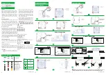
Lens
GR-4
6
0
/WP
(Escape Route)
GR-
4
61/WP
(Anti-Panic Area)
ATTENTION!!!
During installation follow this light direction.
Corridor
lighting
Open
area
lighting
LAMP FAULT BAT. FAULT
CHARGE
TEST
CAUTION : Do not view directly with bare eyes.
The light source of this luminaire is not replaceable when the light source reaches its end of life the whole
luminaire shall be replaced.
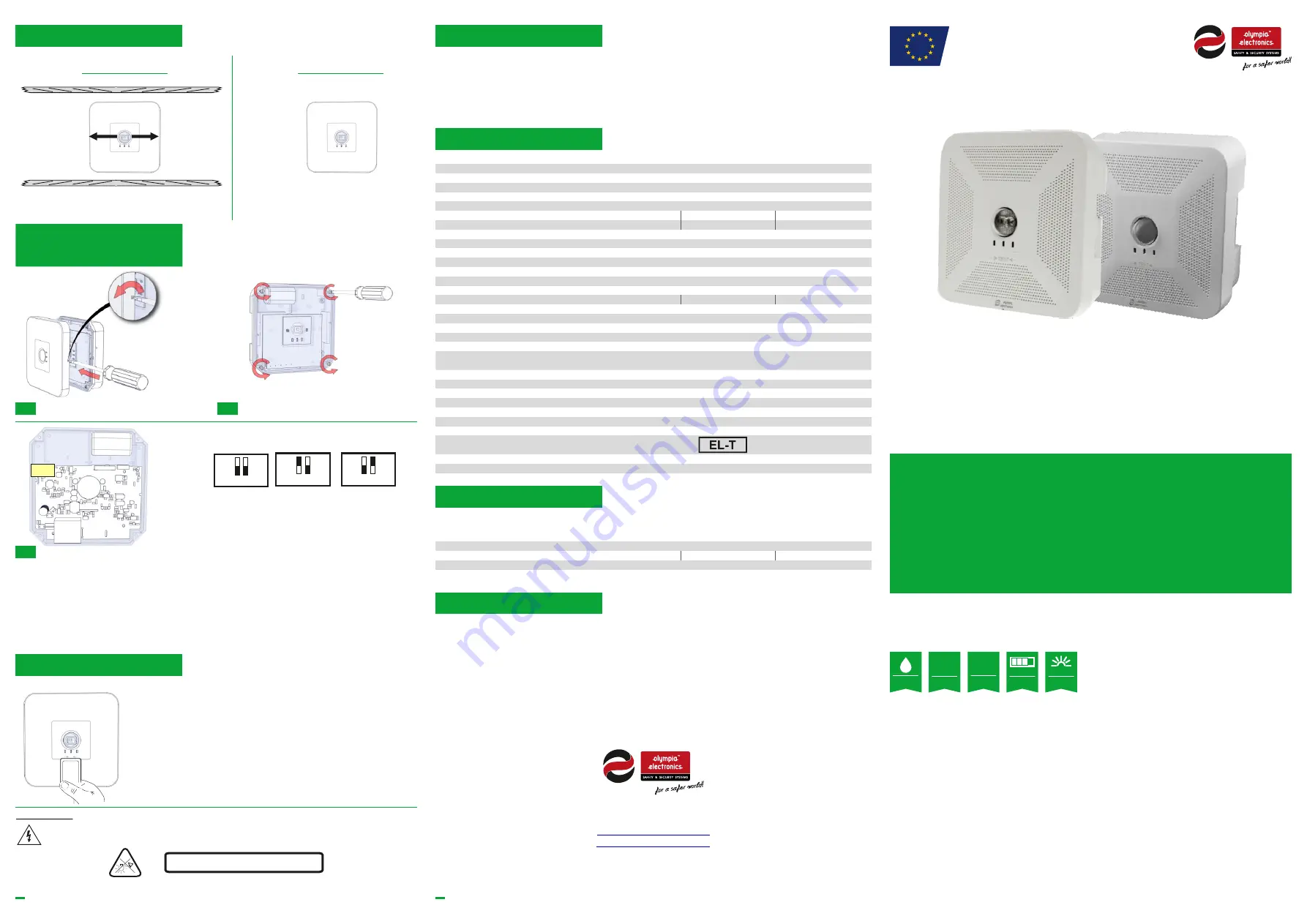
GR-460/WP & GR-461/WP
SELF TESTING MAINTAINED/NON MAINTAINED
EMERGENCY CEILING MOUNTED LUMINAIRES WITH LENS
FOR ESCAPE ROUTE OR ANTIPANIC AREA
LAMP FAULT BAT. FAULT
CHARGE
LAMP FAULT BAT. FAUL
T
CHARGE
9234
60000
_09_00
1
9234
60
00
0
_09_00
1
4
5
GR-
4
60/WP & GR-461/WP
Magnetic Switch Usage
Operation Mode &
Autonomy Duration
Olympia Electronics S.A.
65 °C max. across the board
2.7-3.3V DC
1h: 2.1W
3h: 0.9W
8h: 0.25W
2806183
Thank you for your trust in our products
Olympia Electronics - European manufacturer
For
Manual Operational Test
, you must place the card in front of the TEST
indicator and remove it immediately.
For
Manual Capacity Test
, you must place the card in front of TEST
and
hold it for 5 to 10 seconds.
Test
operations with the A-1900 card (not included and available
after
request).
ATTENTION!!!
Fixed connection between main pcb and led module
Warranty
Technical Characteristics
LED Characteristics
MANUFACTURER
MODEL NUMBER
VOLTAGE RANGE
CONNECTIONS
NOMINAL POWER
TEMPERATURE (tc)
European
manufacturers
IP
65
Non
maintained
NM
Maintained
Μ
320/150/50lm
Light output
1h/
3
h/8h
Duration
Olympia Electronics reserves the right to repair or to replace the returned goods and to or not
charge the
buyer depending on the reason of defection. Olympia Electronics reserves the right to charge or not the
buyer the transportation cost.
Olympia Electronics guarantees the quality, condition and operation of the goods. The period of warranty
is specified in the official catalogue of Olympia Electronics and also in the technical leaflet, which
accompanies each product. This warranty ceases to exist if the buyer does not follow the technical
instructions included in official documents given by Olympia Electronics or if the buyer modifies the goods
provided or has any repairs or re-setting done by a third party, unless Olympia Electronics has fully agreed
to them in writing.
Products that have been damaged can be returned to the premises of our company for
repair or replacement, as long as the warranty period is valid.
72
nd
km
.
O
.
N
.
R
.
Thessaloniki-Katerini
P.C. 60300 P.O. Box 06 Εginio Pierias Greece
www.olympia-electronics.gr
info@olympia-electronics.gr
GR-
4
60/WP & GR-461/WP
220V-240V AC / 50-60Hz
25mA
5.5W / 5.6VA
0.9
10V
1h: 2.1W
1h: 695mA
3h: 0.9W
3h: 295mA
Basic Insulation
Basic Insulation
Deep discharge and overcharge protection
4-6V
1hour / 3 hours / 8 hours
IP65
5 to 40°C
Up to 95%
ABS/PC, PC
500gr
3 years (1 year for the battery)
1 white power LED
Charge, Lamp Fault, Battery Fault, Test Magnetic Switch
EN 60598-1, EN 60598-2-22, EN 55015, EN 61547
EN 61000-3-2, EN 61000-3-3, EN62311
300lm / 1h: 320lm, 3h: 150lm, 8h: 50lm
23hours
100 - 130mA
3h: 190 - 280mA
8h: 70 - 115mA
1h: 460 - 645mA
4.8V / 1.2Ah (4KRMT 15/51)
500V
8h: 0.25W
8h: 95mA
OPERATION VOLTAGE
MAXIMUM POWER CONSUMPTION
BATTERY (Ni-MH)
INSULATION BETWEEN SUPPLY & CONTROL TERMINALS
INSULATION BETWEEN SUPPLY & BATTERY CIRCUIT
WORKING VOLTAGE AT WHICH THE INSULATION IS DESIGNED
MINIMUM POWER FACTOR (
λ)
Irated
Prated
U-OUT
MAXIMUM SUPPLY CURRENT
BATTERY PROTECTION
BATTERY VOLTAGE RANGE
CHARGE TIME
MINIMUM DURATION
LIGHT SOURCE
DEGREES OF COVER PROTECTION
PRODUCED IN ACCORDANCE WITH
OPERATION TEMPERATURE RANGE
RELATIVE HUMIDITY
CONSTRUCTION MATERIAL
EXTERNAL DIMENSION (L x W x H)
WEIGHT
GUARANTEE
Controlgear is suitable for LED module only
The controlgear has mains-connected windings of transformer
INDICATIONS
BATTERY CHARGE CURRENT RANGE
BATTERY DISCHARGE CURRENT RANGE
LIGHT SOURCE LUMINOUS FLUX (MAINS / EMERGENCY)
CONTROL GEAR WITH AUTOMATIC
TEST FUNCTION
15
8
x 15
8
x 60.4mm
(without decorative bezel) - 1
95
x
195
x 60.4 (with decorative bezel)
2
1
1h
(default position)
3h
8h
Dip Switch Positions
Autonomy duration selection
Technical label installation
The user can select one of the 3 available minimum autonomy duration 1hour, 3hours and 8hours. The selection
must be done while the luminaire is disconnected from AC and battery supplies. The selection is achieved through
Switches 1 & 2 of DS1.
Two additional labels are included in the package, one for 3 hours duration (180) and one for 8 hours duration (480).
Depending on the selected duration, the installer must cover the default 1 hour (60) printing with one that has the
required duration. Please take notice of the orientantion of the label.
3
ON
1 2
ON
2
1
ON
2
1
DS1
A-1900
Battery Replacement
It can be done only by a competent person and after the mains interruption
.
3
.
Disconnect the connector and remove the old battery.
4
.
Connect the new battery with the same type
and place it in
the position of the old one.
5
.
Replace the removed parts
and power the device.
1. Detach the front cover by applying pressure using a flat blade screw driver. Next, unfasten the four retaining screws
without removing them and remove the diffusor.


