background image

MAINTENANCE MANUAL

CLV-160

Summary of Contents for CLV-160

Page 1: ...MAINTENANCE MANUAL CLV 160...

Page 2: ...knowledge and technique We recommend to contact the Olympus agent in your country when the product goes out of order For remodeling or repairs to be done by the agent or person not authorized by us w...

Page 3: ...CLV 160 CONTENTS 1 SPECIFICATIONS 2 CONNECTION DIAGRAM 3 BLOCK DIAGRAM 4 TROUBLESHOOTING 5 DISASSEMBLING PROCEDURE 6 ASSEMBLING PROCEDURE 7 EXPLODED PARTS DIAGRAM 8 PARTS LIST 1 1 2 1 3 1 4 1 5 1 6 1...

Page 4: ...ial filter if necessary One special filter frame is provided 2 The emergency lamp is automatically placed into the optical axis when the diagnostic lamp does not light Xenon short arc lamp with an ell...

Page 5: ...the lamp When the emergency lamp is lit LED is lit Storage of set values The setting is stored before the power switch is turned off and when the power switch is turned off Setting of manual auto lig...

Page 6: ...ipment safety test JIST1005 medical electric equipment manual Russia GOST R 4 Other countries Nothing Classification of medical 100 V type BF type instruments instruments 200 V type BF type fitting pa...

Page 7: ...rd Cord set with a 3 core hospital grade plug 100V 3 pin inlet 3 core cord plug less cord set 200V Fuse capacity 100V type BA Littel 313008 or the equivalent 200V type 5A Littel 218005 or the equivale...

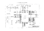
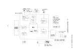
Page 8: ...2 C O N N E C T I O N D I A G R A M 2 1...

Page 9: ...uit Front panel control Pump drive control PUMP Buzzer control MPU RAM ROM DIAPHRAGM MOTOR M Brightness adjustment circuit Ignition control AUX CONNECTOR LIGHT CONTROL CONNECTOR SCOPE CONNECTOR THERMA...

Page 10: ...e visual field is dark or too bright LED does not light or LED indication does not change even if the switch is depressed Emergent light check Manual brightness adjustment check Automatic brightness a...

Page 11: ...ing fan rotate Y e s N o Check the supply voltage Check the power cord Check the inlet plug Mal connection Yes Does the LED above the switch light up No Is the lamp cover closed Yes Does the LED above...

Page 12: ...es the LED above the switch light up No Replace the Replace the filter board Yes Does the LED above the switch light up N o N o Is the output voltage of the power supply unit correct Replace the UPCL1...

Page 13: ...s the xenon lamp light up No Yes Check the lamp mounting The lamp is correctly mounted The heat compound is correctly painted Yes Does the xenon lamp light up No Replace the lamp by a brand new one Y1...

Page 14: ...be forcibly turned off Replace the igniter in the switching power supply Yes Set the J4 2 pin of UPCL16CR00 to L level GND Replace the UPCL16CR00 Replace the main board Yes Does the xenon lamp light...

Page 15: ...by the emergency lamp when it goes out after once ignition up No Yes Does the audible warning sound when the emergency lamp lights up No C Yes Cooling fan operation check N o Does the lamp go out aft...

Page 16: ...place the switching power supply No Does the lamp go out after once ignition up Yes Replace the UPCL16CR00 Replace the main board Check the power cord for breakage or contact failure Does the lamp go...

Page 17: ...annot be connected Does the scope correctly connected Yes No Is the applicable scope used No Yes Replace the scope by an applicable scope Is the scope connector deviated No Yes Replace the scope Check...

Page 18: ...he lamp housing fan Does the switching power supply fan operate Y e s N o Switching regulator UPCL16CR00 F a n UPCL16CR00 No Replace the UPCL16CR00 Replace the main board Check the connector for conta...

Page 19: ...htness reduced to the minimum when the scope is removed No Check the scope detection mechanism and the diaphragm mechanism The metal plate part deformed or caught The diaphragm is deformed or caught Y...

Page 20: ...eck the harness connection Check the hose connection Check the non return valve for clogging Check the rubber part of the air supply mouthpiece UPCL16CR00 Front panel U Does the pump operate and air i...

Page 21: ...r supply volume changed at H M L of the air supply switch No Yes Yes Is the output voltage changed when the air supply volume is changed No Replace the UPCL16CR00 Replace the W12M013A Replace the main...

Page 22: ...ct no to be close Is the temperature switch turned off at the temperature No switch operating temperature Yes Is the temperature switch turned off at the Yes temperature lower than the temperature swi...

Page 23: ...on No Yes Check the harness connection UPCL16CR00 Stepping motor UPCL16CR00 Front panel U Check that the turret plate is not extremely loose Yes Does the turret return to the initial position No Repla...

Page 24: ...ED Check the harness connection UPCL16CR00 Front panel U Does the turret Yes plate rotate when the filter switch is operated No Yes Does the turret plate rotate when the filter switch is operated No R...

Page 25: ...tness in manual mode Is light emitted from the scope Yes No Yes Yes Yes Yes Check the power supply Is light emitted from the scope No Check the lamp Is light emitted from the scope No Check the lamp b...

Page 26: ...ustment switch No Check the harness connection Check the diaphragm mechanism UPCL16CR00 UPNS6OU Diaphragm blade is deformed or caught Yes Is the diaphragm controlled with the brightness adjustment swi...

Page 27: ...priate Usually 0 is standard Yes Does the automatic brightness adjustment work correctly No Check the harness connection UPCL16CR00 UPNS6OU Yes Does the automatic brightness adjustment work correctly...

Page 28: ...orrectly No Yes Is INDEX optimum Usually 0 is standard Yes Does the automatic brightness adjustment workcorrectly No Check the connection of the Mal connection light control cable MH 966 Contact failu...

Page 29: ...CLV 160 B Yes Does the automatic brightnessadjustment work correctly No Replace the UPCL16CR00 Replace the main board Yes Does the automatic brightness adjustment workcorrectly No Check the connected...

Page 30: ...p brightness optimum No Check INDEX Set to MAX Does the diaphragm work normally No Yes Yes Is the lamp brightness optimum No Check that the standard filter supplied with the main unit is set in the st...

Page 31: ...LED lit normally with a lighting noise No Yes Yes Is LED normal except the lighting noise No Check the connector contact Main board Front panel Yes Is LED lit normally with a lighting noise No Replac...

Page 32: ...lace the W12M018A Replace the emergency lamp harness Is the emergency lamp LED lit on the front panel Yes Does the emergency lamp state signal detect the defect Yes No J4 7 pin of the main board is H...

Page 33: ...the emergency lamp lit when the main lamp is not lit Yes Replace the UPCL16CR00 Replace the main board Yes Is the emergency lamp lit when the main lamp is not lit No Replace the UPCL16PS10 20 Replace...

Page 34: ...heck The values set before the power is turned off are not stored when the power is turned off Are the values set before turning off of the power held when the power is turned on No Yes Replace the UP...

Page 35: ...en if the lamp life meter reset switch Does LED indicate zero when the lamp life meter reset switch is depressed N o Yes No Is the reset switch held depressed TROUBLESHOOTING CLV 160 Yes Hold the rese...

Page 36: ...n check transillumination switch is depressed Panel operation check Filter switching operation check Manual brightness adjustment check Is the brightness increased to the maximum when the transillumin...

Page 37: ...oltage parts 3 Cover screws with a toothed lock washer to suppress a radiation noise Use the specified parts The parts used in this unit are designed protective against vibration heat and high voltage...

Page 38: ...the screws from the side panel Phillips screwdriver No 2 HCBK3x6SA x 10 4 Remove the top cover 2 Front panel 1 Remove the screws that secure the front panel to the chassis Phillips screwdriver No 2 C...

Page 39: ...ss from the clamp 2 Remove the harness wound around the spiral from the pump BK Phillips screwdriver No 2 CCUK3x6SZ x 2 3 Remove the spiral from the harness except the scope detection harness from the...

Page 40: ...Remove the core and remove the emergency lamp housing from the power supply unit 2 Remove the shield cover Phillips screwdriver No 2 CCUK3x4SZ x 4 3 Remove the shield PS plate Phillips screwdriver No...

Page 41: ...rom the chassis Phillips screwdriver No 2 CUKSK3x6SZ x 2 7 Switch collar and pushbutton switch 1 Remove the switch washer switch plate and switch plate collar from the chassis 2 Remove the screws and...

Page 42: ...rewdriver 5 5mm C6N3SZ x 3 5 Remove the turret unit from the optical base Phillips screwdriver No 2 CCUK3x6SZ x 3 When assembling tighten the screw A together with the earth strap as shown on the left...

Page 43: ...ee the drawing below chassis 11 Remove the electrode F from the optical base 12 Remove the sink holder spring from the optical base Phillips screwdriver No 2 CCUK3x4SZ x 2 13 Remove the cable from the...

Page 44: ...use the special tool Be careful not to be injured Some metallic parts have sharp corner or edge Be careful when handling such parts Be sure to observe the specified torque and dimensions Observe the...

Page 45: ...EXPLODED PARTS DIAGRAM CLV 160 7 EXPLODED PARTS DIAGRAM 7 1...

Page 46: ...EXPLODED PARTS DIAGRAM CLV 160 7 2...

Page 47: ...EXPLODED PARTS DIAGRAM CLV 160 7 3...

Page 48: ...EXPLODED PARTS DIAGRAM CLV 160 7 4...

Page 49: ...EXPLODED PARTS DIAGRAM CLV 160 7 5...

Page 50: ...EXPLODED PARTS DIAGRAM CLV 160 7 6...

Page 51: ...EXPLODED PARTS DIAGRAM CLV 160 7 7...

Page 52: ...CLASS 2 A2 HOLDER 100V CLASS 2 A1 INLET 4 A1 HOUSING 3 D1 BINDER 4 A4 CABLE HOLDER 5 C3 CABLE HOLDER 3 D1 BINDER 3 B4 CLAMPER 5 C3 CABLE HOLDER 4 A1 HALOGEN 2 A2 CABLE 6 B2 INNTER LOCK SW 6 B2 PUSH B...

Page 53: ...E 3 B3 INSULATOR 6 B1 COVER 6 A2 BRACKET 5 C3 BRACKET 5 D2 COIL S 5 D2 COIL M 6 D1 SHIELD PLATE 6 A3 BRACKET 1 C2 TOP COVER 1 A2 HOT SEAL 1 C2 TANK HOLDER 4 D2 TUBE 3 A2 HINGE 3 B2 HOLDER 3 A2 WASHER...

Page 54: ...TURRET U 4 A1 W12M018A 4 B2 FILTER STU 4 A3 FILTER OPU 7 A3 W12M017A 4 B3 LIMIT SWU 3 D2 W12M019A 3 B3 W12M020A 3 A1 HEAT SINK FU 3 A1 HEAT SINK RU 5 D1 PUMP BKU 5 C1 W12M013A 7 A1 W12M001A 7 A1 W12M...

Page 55: ...NDEX 2 A1 3 C2 3 B2 4 B2 4 A2 1 A3 1 A4 6 B3 3 B3 3 A2 1 A1 2 D2 2 C2 5 A1 PARTS NAME E SPECIFICATION SCREW SCREW SCREW SCREW SCREW SCREW SCREW SCREW E RING E RING SCREW WASHER WASHER SCREW T2CCUK3x8S...

Page 56: ...MAD MEDICAL INSTRUMENT EQUIPMENT LTD Keymad House Stock Road Southend on Ses Essex SS2 5QH United Kingdom OLYMPUS SINGAPORE PTE LTD BLK 211 Henderson Road No 14 02 Henderson Industrial Park Singapore...

Reviews: