background image


DMTA031-01EN — Rev. B
October 2014

InterBox

User’s Manual

This instruction manual contains essential information on how to use this Olympus product safely and effectively. 
Before using this product, thoroughly review this instruction manual. Use the product as instructed.

Keep this instruction manual in a safe, accessible location.

Summary of Contents for InterBox EIB-T-8-M-15-OM

Page 1: ...nstruction manual contains essential information on how to use this Olympus product safely and effectively Before using this product thoroughly review this instruction manual Use the product as instructed Keep this instruction manual in a safe accessible location ...

Page 2: ...sure the accuracy of the information contained therein and corresponds to the version of the product manufactured prior to the date appearing on the title page There could however be some differences between the manual and the product if the product was modified thereafter The information contained in this document is subject to change without notice Part number DMTA031 01EN Rev B October 2014 Pri...

Page 3: ...n 7 Presence of Visual Interferences or Phantom Spots 8 Safety Symbols 8 Safety Signal Words 9 Note Signal Words 9 Safety 10 Warnings 10 Equipment Disposal 11 CE European Community 11 WEEE Directive 11 EMC Directive Compliance 12 Warranty Information 12 Technical Support 13 Introduction 15 1 Overview 17 2 Connections and Cables 19 2 1 Connections to the Acquisition Unit 19 2 2 Power Cable Connecto...

Page 4: ...Probe Connectors 23 2 6 Connecting the Phased Array Connectors 24 2 7 InterBox Installation 27 3 Maintenance 29 3 1 Preventive Maintenance 29 3 2 Unit Cleaning 29 4 Specifications 31 4 1 TRPP 5810 Specifications 32 4 1 1 12 V Connector 33 4 1 2 P and R Connectors 34 4 2 InterBox Connector Configurations and Ordering Numbers 34 List of Figures 37 List of Tables 39 Index 41 ...

Page 5: ...bbreviations v List of Abbreviations CE European Community LED light emitting diode N A not applicable PA phased array PVC polyvinyl chloride TOFD time of flight diffraction UT ultrasonic testing WEEE waste electrical and electronic equipment ...

Page 6: ...DMTA031 01EN Rev B October 2014 List of Abbreviations vi ...

Page 7: ...e attached to the instrument at the locations shown in Figure i 1 on page 1 If any or all of the labels or symbols are missing or illegible please contact Olympus Figure i 1 Labels location Location of TRPP rating plate label see Table 1 on page 2 Location of InterBox rating plate label see Table 1 on page 2 ...

Page 8: ...s product conforms to all the applicable directives of the European Community See the Declaration of Conformity for details Contact your Olympus representative for more information The WEEE symbol indicates that the product must not be disposed of as unsorted municipal waste but should be collected separately The direct current symbol S N The serial number ...

Page 9: ...the risk of electric shock do not touch the inner conductor of the LEMO 00 P1 OUT and P2 OUT connectors for the TRPP 5810 pulser preamplifier Up to 200 V can be present on the inner conductor CAUTION TRPP 5810 LEMO 00 P1 OUT and P2 OUT connectors inner conductors ...

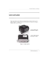
Page 10: ...DMTA031 01EN Rev B October 2014 Labels and Symbols 4 ...

Page 11: ...ls Do not use the InterBox for any purpose other than its intended use It must never be used to inspect or examine human or animal body parts Instruction Manual This instruction manual contains essential information on how to use this Olympus product safely and effectively Before using this product thoroughly review this instruction manual Use the product as instructed Keep this instruction manual...

Page 12: ...se equipment malfunction and or damage or human injury Table 2 Ancillary equipment Part number Item number Description TRPP A PWRC FLT 15M U8120098 15 m long power cable linking TRPP 5810 or PR06 04 to Focus LT TRPP A PWRC AC 15M U8767233 Transformer 120 VAC to 240 VAC input to 12 VDC output with 15 m power supply cable TRPP A PWRC OM 10M U8775118 10 m power supply cable linking TRPP 5810 to an Om...

Page 13: ...VDC output with 5 m power supply cable TRPP A PWRC OM 25M U8775216 25 m power supply cable linking TRPP 5810 to an OmniScan TRPP A PWRC AC 25M U8775217 Transformer 120 VAC to 240 VAC input to 12 VDC output with 25 m power supply cable TRPP A PWRC OM 30M U8775221 30 m power supply cable linking TRPP 5810 to an OmniScan TRPP A PWRC AC 30M U8775222 Transformer 120 VAC to 240 VAC input to 12 VDC outpu...

Page 14: ... physical features of the inspected part Safety Symbols The following safety symbols might appear on the instrument and in the instruction manual General warning symbol This symbol is used to alert the user to potential hazards All safety messages that follow this symbol shall be obeyed to avoid possible harm or material damage High voltage warning symbol This symbol is used to alert the user to p...

Page 15: ...ed to could result in death or serious personal injury Do not proceed beyond a WARNING signal word until the indicated conditions are fully understood and met The CAUTION signal word indicates a potentially hazardous situation It calls attention to an operating procedure practice or the like which if not correctly performed or adhered to may result in minor or moderate personal injury material dam...

Page 16: ...gs In addition note the external markings on the instrument which are described under Safety Symbols Warnings General Warnings Carefully read the instructions contained in this instruction manual prior to turning on the instrument Keep this instruction manual in a safe place for further reference Follow the installation and operation procedures It is imperative to respect the safety warnings on th...

Page 17: ...e disposing of the InterBox check your local laws rules and regulations and follow them accordingly CE European Community WEEE Directive This device complies with the requirements of both directive 2004 108 EC concerning electromagnetic compatibility and directive 2006 95 EC concerning low voltage The CE marking indicates compliance with the above directives In accordance with European Directive 2...

Page 18: ...idence of external or internal damage that might have occurred during shipment Immediately notify the carrier making the delivery of any damage because the carrier is normally liable for damage during shipment Retain packing materials waybills and other shipping documentation needed in order to file a damage claim After notifying the carrier contact Olympus for assistance with the damage claim and...

Page 19: ...customer service and product support If you experience any difficulties when using our product or if it fails to operate as described in the documentation first consult the user s manual and then if you are still in need of assistance contact our After Sales Service To locate the nearest service center visit the Service Centers page at http www olympus ims com ...

Page 20: ...DMTA031 01EN Rev B October 2014 Important Information Please Read Before Use 14 ...

Page 21: ...nnections between the scanner and its acquisition instrument To help you understand and safely use the InterBox this manual contains an equipment overview connection details maintenance instructions and detailed specifications Four InterBox models are available for configurations to suit different equipment applications In this manual the InterBox model EIB T 8 M 15 OM is shown because it presents...

Page 22: ...DMTA031 01EN Rev B October 2014 Introduction 16 ...

Page 23: ...rray probes up to two pairs of TOFD probes and up to eight conventional UT transducers to the InterBox The connections are transmitted to the acquisition unit through a single 128 element cable with an OmniScan or Hypertronics connector Figure 1 1 InterBox model EIB T 8 M 15 OM Connector locations 2 PA probe connections 8 conventional UT connections optional 4 TOFD connections optional Power conne...

Page 24: ...r receiver extension box and the PA probe splitter Depending on the model the InterBox integrates a splitter for phased array probes a remote pulser preamplifier for TOFD inspections or multiple UT channels and is therefore well suited for certain applications that require a combination of these features For each of these configurations two cable types are available a flexible PVC cable and a meta...

Page 25: ... are provided and therefore the connection procedures may vary 2 1 Connections to the Acquisition Unit The InterBox is connected to an acquisition instrument by using an OmniScan or Hypertronics connector and cable The cable s outer material is either metallic armored or PVC coated see Figure 2 1 on page 19 Figure 2 1 The acquisition data cable Acquisition data cable ...

Page 26: ...2 3 on page 21 Figure 2 2 Aligning the marks for the power connector Once the InterBox is correctly connected to an electric power source the red LED illuminates see Figure 2 3 on page 21 All InterBox models equipped with TRPP 5810 come with two power cables The first power cable allows the InterBox to be powered by an OmniScan acquisition unit The second power cable allows the InterBox to be powe...

Page 27: ...section labeled TRPP 5810 see Figure 2 4 on page 21 Figure 2 4 The TOFD connections On the TRPP 5810 module two connectors are for pulser outputs and two are for receiver inputs This enables the InterBox to drive two pairs of TOFD probes simultaneously The red LED illuminates when power is connected InterBox with TRPP 5810 offers two different cables for a power source connection OmniScan or AC po...

Page 28: ...identify the receiver inputs These codes as well as the channel numbers are marked next to each connector see Figure 2 4 on page 21 Figure 2 5 The label with probe connection diagram Table 3 InterBox Pinout for the P and R connectors Connector I O Description P1 OUT and P2 OUT Output These P connectors are used to transmit the signals to two conventional probes R1 IN and R2 IN Input These R connec...

Page 29: ...ector Figure 2 6 The conventional UTconnections The power output from the conventional UT channels is limited to 80 V This is because these channels are connected to a phased array instrument which imposes this voltage limit 2 5 Phased Array Probe Connectors Two phased array connector receptacles are mounted on the top of the InterBox see Figure 2 7 on page 24 Rubber covers protect the receptacles...

Page 30: ...n each PA range depends on how many channels are used for TOFD and conventional UT connections The maximum total number of channels can be either 64 or 128 depending on the InterBox model For more information about channel numbers refer to Table 10 on page 36 2 6 Connecting the Phased Array Connectors The two InterBox phased array connectors have covers that protect them from dust and other pollut...

Page 31: ...no PA probe connected to the instrument To connect a phased array connector to the InterBox 1 Remove the phased array protective cover see Figure 2 8 on page 25 Figure 2 8 Removing the PA protective covers 2 Align the pins of the phased array connector with the receiving holes on the receptacle see Figure 2 9 on page 26 Pull to unlock If necessary remove two screws to remove the cover ...

Page 32: ...e sure that the connector is aligned straight with respect to the receptacle before pushing it into the receptacle 3 Push the connector into the receptacle to ensure a good connection see Figure 2 10 on page 26 4 Pull down the latch mechanism to lock the connector Figure 2 10 The OmniScan connector pushed in left and locked right ...

Page 33: ...igure 2 11 The mounting bracket for the HSMT manual scanner To install or remove the InterBox 1 Identify a location on the scanner s frame where the InterBox will be installed Ensure that this location allows access to the InterBox s different connectors without limiting the scanner s mobility see Figure 2 12 on page 28 2 Slide the two T nuts into the frame bar of the scanner 3 Move the InterBox a...

Page 34: ...ber 2014 Chapter 2 28 Figure 2 12 The InterBox assembly attached to the scanner 4 Tighten the two thumb screws T nut Thumb screw Mounting bracket Note older version of product is shown but attachment method remains unchanged ...

Page 35: ... that the InterBox functions correctly 3 2 Unit Cleaning The InterBox external surfaces can be cleaned when needed This section provides the appropriate product cleaning procedure To clean the unit 1 Ensure the unit is turned off by removing the source of power 2 Disconnect all cables 3 To bring the instrument back to its original finish clean the housing with a soft cloth 4 To remove persistent s...

Page 36: ...DMTA031 01EN Rev B October 2014 Chapter 3 30 ...

Page 37: ...1 97 in Weight 1 kg 2 2 lb a Operating temperature 10 C to 60 C 14 F to 140 F Storage temperature 20 C to 70 C 4 F to 158 F Relative humidity Up to 85 noncondensing Wet location Yes Altitude Up to 2000 m Outdoor use Yes Pollution level 2 IP rating Splash proofb Designed for IP34 rating Main cable characteristics External material Flexible metallic armored OR PVC jacket Number of elements 64 elemen...

Page 38: ... 12 VDC nominal Current 250 mA max Table 6 TRPP 5810 Receiver preamplifier specifications Voltage gain 40 dB 0 5 dB into 50 Ω at 10 MHz Bandwidth 3 dB 0 5 MHz to 30 MHz with 10 tolerance Input referred noise 2 with 50 Ω source impedance Input output HV protection 300 V peak pulsed for pulse width 500 ns Input impedance 550 Ω 55 Ω Output impedance 50 Ω 5 Ω Crosstalk between channels 100 dB with 10 ...

Page 39: ...051 60 6 2 S Olympus 21AB0132 Figure 4 1 The 12 V connector Input impedance 50 Ω 5 Ω Probe damping Active 50 Ω 5 Ω Minimum pulse width 30 ns 5 ns Maximum pulse width 500 ns 50 ns Repeated pulse width error 10 for pulse width 50 ns otherwise 5 ns with 50 V min input trig voltage Maximum pulse repetition freq PRF 5 kHz for 100 ns pulse width both channels 10 kHz for 100 ns pulse width single channel...

Page 40: ...ivalent W W Fischer S 101 A004 3 0 Olympus 21AB0016 Figure 4 2 The P and R connector 4 2 InterBox Connector Configurations and Ordering Numbers Table 9 on page 35 specifies the total number of connectors for each type of connection that are included on each InterBox model Table 10 on page 36 contains the designated channel numbers for the connectors In the tables the InterBox model numbers are cod...

Page 41: ... 0 4 EIB NT 8 x x xx 2 0 8 EIB64 NT 0 x x xx 2 0 0 EIB64 NT 4 x x xx 2 0 4 EIB64 NT 8 x x xx 2 0 8 EIB64 T 0 x x xx 2 4 0 EIB64 T 4 x x xx 2 4 4 EIB64 T 8 x x xx 2 4 8 EIB T 8 P 5 OM Extension InterBox EIB 128 elements EIB64 64 elements Total number of conventional UT connectors 0 4 or 8 Cable type P Flexible PVC cable M Metal armor outer cover Connector type OM OmniScan standard HY Hypertronics T...

Page 42: ... UT 2 UT 3 UT 4 UT 5 UT 6 UT 7 UT 8 EIB T 0 x x xx 1 62 65 126 63 64 128 127 a a For this table if a table box is empty channel numbering does not apply EIB T 4 x x xx 1 60 65 124 63 64 128 127 61 62 125 126 EIB T 8 x x xx 1 58 65 122 63 64 128 127 59 60 61 62 123 124 125 126 EIB NT 0 x x xx 1 64 65 128 EIB NT 4 x x xx 1 62 65 126 63 64 127 128 EIB NT 8 x x xx 1 60 65 124 61 62 63 64 125 126 127 1...

Page 43: ...th probe connection diagram 22 Figure 2 6 The conventional UT connections 23 Figure 2 7 The protective covers for phased array connectors PA1 and PA2 24 Figure 2 8 Removing the PA protective covers 25 Figure 2 9 Aligning the OmniScan connector 26 Figure 2 10 The OmniScan connector pushed in left and locked right 26 Figure 2 11 The mounting bracket for the HSMT manual scanner 27 Figure 2 12 The Int...

Page 44: ...DMTA031 01EN Rev B October 2014 List of Figures 38 ...

Page 45: ...ox Pinout for the P and R connectors 22 Table 4 InterBox Technical specifications 31 Table 5 TRPP 5810 Power supply 32 Table 6 TRPP 5810 Receiver preamplifier specifications 32 Table 7 TRPP 5810 Pulser specifications 32 Table 8 InterBox Pinout for the 12 V connector 34 Table 9 InterBox Number of connectors 35 Table 10 InterBox Channel numbering 36 ...

Page 46: ...DMTA031 01EN Rev B October 2014 List of Tables 40 ...

Page 47: ...on TRPP 5810 22 phased array probe 23 25 power cable TRPP 5810 20 TOFD probe diagram 22 connector locations 17 connectors 12 V IN pinout 34 references 33 LEMO 00 3 number on InterBox models 35 P connectors pinout 22 references 34 phased array PA1 and PA2 24 probes 23 R connectors pinout 22 references 34 TOFD 21 TRPP 5810 21 conventional UT channel numbering 36 transducer connectors 23 D DANGER sig...

Page 48: ... power cable TRPP 5810 20 power connector 20 power LED 20 power output limit UT connector channel 23 power supply specifications 32 preamplifier specifications 32 precautions safety 10 preventive maintenance 29 probe connection diagram TOFD 22 protective covers water resistant 25 pulser specifications 32 pulser preamplifier connection TOFD 22 R R connectors See connectors rating plate label 2 loca...

Page 49: ...pply specifications 32 pulser 32 pulser outputs P1 and R1 connectors 22 pulser receiver specifications 32 receiver 32 receiver inputs R1 and R2 connectors 22 U unit cleaning 29 use intended 5 UT connectors channel number 23 channel power output limit 23 location 23 W WARNING signal word 9 warnings general 10 misuse of instrument 5 warranty information 12 waste electrical and electronic equipment W...

Page 50: ...DMTA031 01EN Rev B October 2014 Index 44 ...

Reviews: