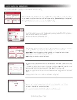
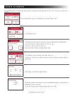
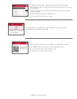
background image


Seam M

ode

OFF                    O

n

Device Ready

Mode

OptiW

eld

Membr

ane

PVC 60 mil

Activations 

Today

                          0 

RB1044USA


Rev. 02222022

153 BOWLES ROAD, AGAWAM, MA 01001  USA

800.633.3800   413.789.0252   RHINOBOND.COM

Non-penetrating fastening system  

for commercial roofing

IMPORTANT!  

Save this manual  

and read it in full  

before use. 

O

WNER

’S

 MANU

AL

Now with advanced OptiWeld Technology for
optimum plate bonding and performance!

Summary of Contents for RhinoBond

Page 1: ...v 02222022 153 BOWLES ROAD AGAWAM MA 01001 USA 800 633 3800 413 789 0252 RHINOBOND COM Non penetrating fastening system for commercial roofing IMPORTANT Save this manual and read it in full before use...

Page 2: ...ttachment to meet FM 1 90 and Eurocode National wind uplift requirements Zero Penetrations The fasteners and plates used are all installed under the membrane so with RhinoBond there are no membrane pe...

Page 3: ...pheres such as in the presence of flammable liquids gases or dust Arcing could occur which could ignite the dust or fumes c Keep children and bystanders away while operating a power tool Distractions...

Page 4: ...the power tool repaired before use Many accidents are caused by poorly maintained power tools Contact OMG Roofing at 800 633 3800 or 413 789 0252 for details e Use the power tool in accordance with t...

Page 5: ...EXTENSION CORD 12 gauge min 100 ft max 1 10V 2 5mm X 30m 16A 230V 3x15 30m 10A 30m PORTABLE GENERATOR POWER SOURCE 5 000W min with 2 20A GFCI Circuits 2 5 KVA min with 16Amp 1 10V protected circuit 2...

Page 6: ...l ActivationsToday 0 Heat Sinks 6 included with a carrying case Activation Button Touchscreen Display Power Cord Height Adjustment for Handle Induction Coil Handle RhinoBond with OptiWeld Tool with ca...

Page 7: ...to protect the insulation from melting On foil faced insulation the recommended minimum cover board is 1 in 38 mm Metal Deck A minimum of 1 inches 38 mm of insulation over a metal deck is required fo...

Page 8: ...RhinoBond tool the main screen will show a status bar indicating tool startup progress If necessary you can calibrate the touch screen at this time To do so touch this screen once to begin the calibra...

Page 9: ...The Power Display shows the line voltage the tool is receiving from the power source The tool requires a minimum of 100 volts to operate effectively Menu Pressing this button will open the menu scree...

Page 10: ...magnetic heat sinks Turn the membrane over to reveal the welded plates and use pliers to peel each plate off to confirm the quality of the welds CAUTION Do not touch welded plate until a magnetic cool...

Page 11: ...minus buttons Push the Save button once the energy setting is set The screen will automatically return to the Device Ready screen The Device Ready screen will display the current energy setting i e 5...

Page 12: ...and mark the energy setting on the membrane for reference Adjust the Energy Level to the next higher setting and repeat the test weld process until all five plates are welded with increasingly higher...

Page 13: ...screen Press the Sound button to change the Activation Complete tone The sound can be enabled by press ing the On button and disabled by pressing the Off button You have a choice of two different tone...

Page 14: ...tton to return to the Device Ready screen Press the back arrow to return to the previous screen From the main Menu press the Help button to access OMG Roofing Products contact information troubleshoot...

Page 15: ...o review the Troubleshooting tips and error message descriptions Press any of the error message buttons to get more information and recommendations Press the back arrow to return to the previous scree...

Page 16: ...LVD 2006 95 EC The following harmonized standards were applied LVD EN60335 1 2012 A11 2014 EN60335 2 45 2002 A2 2012 RhinoBond Induction Welding Tools wielding the CE Mark comply with these harmonize...

Page 17: ...de baja tensi n LVD 2006 95 CE Se aplicaron las siguientes normas armonizadas LVD EN60335 1 2012 A11 2014 EN60335 2 45 2002 A2 2012 Los aparatos de soldadura por inducci n RhinoBond que hacen uso de l...

Page 18: ...onsejos de Soluci n de problemas y las descripciones de los mensajes de error Presione cualquier mensaje de error para obtener m s informaci n y recomendaciones Presione la flecha hacia atr s para reg...

Page 19: ...icio para regresar a la pantalla Aparato listo Presione la flecha hacia atr s para regresar a la pantalla anterior En el Men principal presione el bot n Ayuda para acceder a la informaci n de contacto...

Page 20: ...t n Sonido para cambiar el tono de Activaci n finalizada El sonido puede habilitarse presionando el bot n Encendido y deshabilitarse presionando el bot n Apagado Tiene la opci n de dos tonos diferente...

Page 21: ...marque la configuraci n de energ a en la membrana para referencia Establezca el Nivel de energ a en la siguiente configuraci n superior y repita el proceso de soldadura de prueba hasta que se hayan s...

Page 22: ...e el bot n Guardar luego de establecer la configuraci n de energ a La pantalla regresar autom ticamente a la pantalla Aparato listo La pantalla Aparato listo mostrar la configuraci n de energ a actual...

Page 23: ...disipadores de calor magn ticos Gire la membrana para exponer las placas soldadas y utilice pinzas para despegar cada placa y confirmar la calidad de las soldaduras PRECAUCI N No toque la placa soldad...

Page 24: ...voltaje de la l nea que el aparato recibe de la fuente de la alimentaci n El aparato necesita un m nimo de 100 voltios para funcionar de manera efectiva Men al presionar este bot n se abrir la pantal...

Page 25: ...primera vez la pantalla principal mostrar una barra de estado que indica el avance del encendido Si es necesario puede calibrar la pantalla t ctil en ese momento Para hacerlo toque la pantalla una vez...

Page 26: ...m nimo recomendado es de 1 pulg 38 mm Cubierta met lica Se necesita un aislamiento m nimo de 1 pulg 38 mm sobre una cubierta met lica para una adecuada manipulaci n del aparato INSTALACI N ADECUADA D...

Page 27: ...ati on s To da y 0 Disipadores de calor 6 incluidos con estuche para transporte Perilla de encendido Pantalla t ctil Cable el ctrico Ajuste de la altura de la manija Bobina de inducci n Manija RhinoB...

Page 28: ...A 50 60 Hz 220 V 50 Hz CABLE DE EXTENSI N Calibre 12 m n 100 pies m x 1 10 V 2 5 mm x 30 m 16 A 230 V 3 x 15 30 m 10 A 30 m FUENTE DE ALIMENTACI N CON GENERADOR PORT TIL 5000 W m n con 2 circuitos GF...

Page 29: ...are el aparato el ctrico antes de utilizarlo Muchos accidentes son provocados por aparatos el ctricos con un mantenimiento incorrecto P ngase en contacto con OMG Roofing al 800 633 3800 o al 1 413 789...

Page 30: ...genere un arco el ctrico lo que puede encender el polvo o los gases c Mantenga a los ni os y transe ntes alejados mientras utiliza el aparato el ctrico Las distracciones pueden provocar que pierda el...

Page 31: ...n el acoplamiento mec nico para cumplir con los requisitos contra succi n del viento de FM 1 90 y el Euroc digo nacional Sin penetraciones todos los sujetadores y placas utilizados est n instalados de...

Page 32: ...22 153 BOWLES ROAD AGAWAM MA 01001 EE UU 800 633 3800 1 413 789 0252 RHINOBOND COM Sistema de fijaci n no penetrante para techados comerciales IMPORTANTE Conserve este manual y l alo completo antes de...

Reviews: