background image

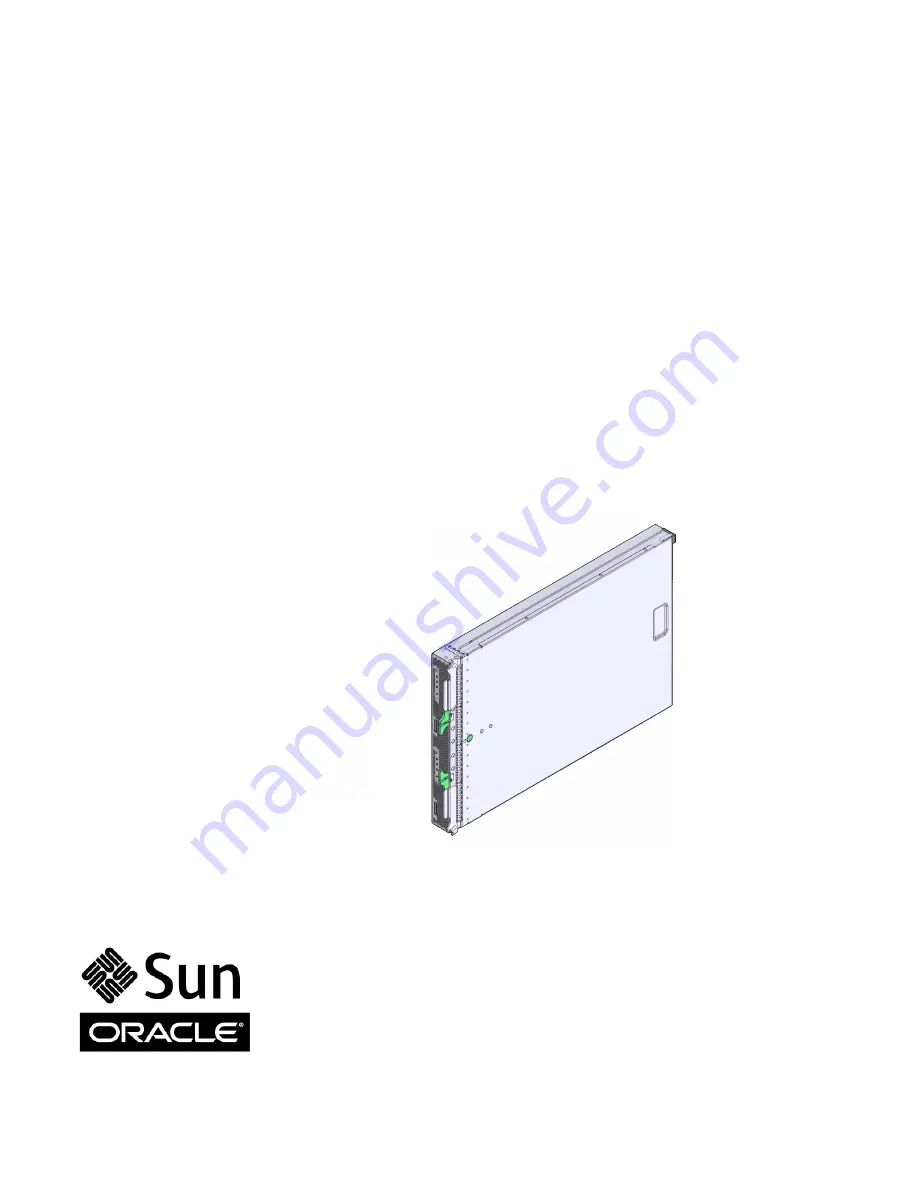
Sun Blade X6275 Server Module

Service Manual

Part No.: Part No. 820-6849-16
September 2013, Rev A

Summary of Contents for Sun Blade X6275

Page 1: ...Sun Blade X6275 Server Module Service Manual Part No Part No 820 6849 16 September 2013 Rev A ...

Page 2: ...rough X Open Company Ltd This software or hardware and documentation may provide access to or information on content products and services from third parties Oracle Corporation and its affiliates are not responsible for and expressly disclaim all warranties of any kind with respect to third party content products and services Oracle Corporation and its affiliates will not be responsible for any lo...

Page 3: ...M Node Numbering 1 5 1 1 4 About the Sun Blade Modular System Chassis 1 7 1 1 4 1 Sun Blade 6048 Modular System Chassis 1 7 1 1 4 2 Sun Blade 6000 Modular System Chassis 1 7 1 1 5 About the Chassis Monitoring Module CMM 1 7 1 2 Specifications 1 8 1 2 1 Server Module Boards 1 8 1 2 2 Dimensions 1 9 1 2 3 Environmental Specifications 1 9 1 2 4 Customer Replaceable Units CRUs and Field Replaceable Un...

Page 4: ...Module From the Sun Blade Chassis 2 7 2 6 Performing Electrostatic Discharge and Antistatic Prevention Measures 2 9 2 6 1 Electrostatic Discharge Safety Measures 2 9 2 6 1 1 Using an Antistatic Wrist Strap 2 9 2 6 1 2 Using an Antistatic Mat 2 10 2 6 2 ESD Handling Procedure 2 10 2 7 Removing the Server Module Top Cover 2 11 2 8 Using the Multi Port Dongle Cable 2 12 2 8 1 Connecting the DB9 to RJ...

Page 5: ...eat Sink 3 22 3 4 Replacing the SP FRU 3 25 3 5 Replacing the Motherboard Assembly FRU 3 27 3 6 Servicing the System Battery CRU 3 30 3 6 1 Removing and Replacing the RTC Battery 3 30 3 7 Resetting Passwords and Clearing CMOS NVRAM 3 33 3 7 1 Overview 3 33 3 7 2 Clearing NVRAM using BIOS 3 34 3 7 3 Resetting BIOS Passwords and NVRAM Using a Jumper 3 34 3 8 Recovering from Corrupt Service Processor...

Page 6: ...g On the Server Module 4 4 A BIOS Screens A 1 A 1 Configuring BIOS Settings A 1 A 1 1 About BIOS A 1 A 1 2 Using BIOS Menu Items A 2 A 1 3 BIOS Setup Utility Screens Overview A 3 A 2 BIOS Setup Menu Screens A 5 A 2 1 BIOS Main Menu Screens A 5 A 2 2 BIOS Advanced Menu Screens A 6 A 2 3 BIOS PCI Menu Screens A 15 A 2 4 BIOS Boot Menu Screens A 17 A 2 5 BIOS Security Menu Screens A 20 A 2 6 BIOS Chi...

Page 7: ...rver Module Service Manual Chapters Chapter Describes Chapter 1 Introduction to the Sun Blade X6275 Server Module provides an overview of the system including front and back panel features This chapter also contains illustrations showing system components Chapter 2 Preparing to Service the System describes the steps necessary to prepare the system for service Chapter 3 Servicing Server Module Comp...

Page 8: ...ng Started Guide 820 6847 Late breaking information Sun Blade X6275 Server Module Product Notes 820 6853 Installation Sun Blade X6275 Server Module Installation Guide 820 6977 OS installation Sun Blade X6275 Server Module Linux Operating System Installation Guide 820 6848 Sun Blade X6275 Server Module Windows Operating System Installation Guide 821 0081 Service processor Sun Integrated Lights Out ...

Page 9: ...reduce the risk of electric shock and danger to personal health follow the instructions TABLE P 3 Sun Blade X6275 Server Module Server Online Documents Function URL Description Documentation http docs sun com Navigate to the Sun Blade X6275 Server Module document page and then download PDF and view HTML docu ments Support http www sun com support Obtain technical support and download patches Train...

Page 10: ...rested in improving the product documentation and welcome your comments and suggestions You can submit comments by clicking the Feedback link at http docs oracle com Please include the title and part number of your document with your feedback Sun Blade X6275 Server Module Service Manual 820 6849 16 ...

Page 11: ...n page 1 8 Section 1 3 Illustrated Parts Breakdown on page 1 12 Section 1 4 Sun Blade X6275 server module Front Panel LEDs and Features on page 1 13 Section 1 5 Sun Blade X6275 server module Rear Panel Features on page 1 15 1 1 Sun Blade X6275 server module Overview The following topics are covered Section 1 1 1 Product Description on page 1 2 Section 1 1 2 Product Features on page 1 3 Section 1 1...

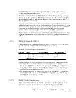
Page 12: ...subsystem Both compute nodes in the Sun Blade X6275 server module have their own ILOM service processor based on the AST2100 chip Each node includes a Sun Flash Module which provides a reliable and secure boot source for the node There are two versions of the Sun Blade X6275 server module The Sun Blade X6275 1GbE Server Module is supported in the Sun Blade 6000 modular system chassis and in the Su...

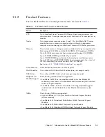
Page 13: ...r channel 3 channels per installed processor Up to 48 GB using 4GB DDR3 DIMMs per compute node for a total of 192 GB of memory per server module for 8 GB DIMMs See Section 3 1 2 DDR3 DIMM Guidelines on page 3 5 Video Memory 8 MB Maximum resolution 1280x1024 pixels Flash Modules Two on board 24 GB Sun Flash Modules one per compute node USB Drives Two on board USB 2 0 drive slots one per compute nod...

Page 14: ...ideo mouse and storage KVMS over IP See Section 1 1 3 About ILOM on page 1 4 for more ILOM information Front Panel I O Two Universal Connector Ports UCP one per compute node are available for use with the multi port dongle cable The dongle cable provides the following interface connections VGA graphics Serial port Dual USB ports keyboard mouse USB disk See Section 2 8 2 Attaching a Multi Port Dong...

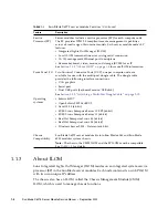
Page 15: ...tegrated Lights Out Manager documentation collection 1 1 3 1 ILOM 2 0 and ILOM 3 0 The Sun Blade X6275 can be equipped with ILOM 2 0 or ILOM 3 0 The SP ILOM must be matched to the CMM ILOM and the chassis as follows In some instances ILOM 2 0 and ILOM 3 0 work differently The differences are noted where they occur If no difference is noted they work identically For more on ILOM 2 0 see the Sun Int...

Page 16: ...flected in the following CMM ILOM features The SYS SLOTID target is different for the two blade ILOMs The chassis CMM ILOM provides separate targets for each blade For example if the blade is in slot 6 then the CMM ILOM provides CH BL6 and CH BL18 or CH BL16 The CMM ILOM web interface provides separate management displays for the two blade ILOMs using the two slot IDs For more information see the ...

Page 17: ...de the chassis before you power on ILOM does not recognize node 1 For ILOM 3 0 systems this requirement does not apply 1 1 4 2 Sun Blade 6000 Modular System Chassis The Sun Blade 6000 modular system chassis holds up to 10 Sun Blade X6275 server modules for a maximum of 20 compute nodes per Sun Blade 6000 modular system chassis For more information refer to the Sun Blade 6000 Modular System Chassis...

Page 18: ... listed in TABLE 1 3 TABLE 1 3 Server Module Boards Board Description Reference Motherboard The motherboard includes four CPU module sockets slots for 24 DDR3 DIMMs slots for flash modules slots for USB drives I O chipsets and a chassis midplane connector Section 3 5 Replacing the Motherboard Assembly FRU on page 3 27 SP board The service processor board subsystem includes independent integrated l...

Page 19: ... fans and air openings If necessary clean systems by brushing or blowing contaminants or carefully vacuuming contaminants from the system TABLE 1 4 Sun Blade X6275 server module Dimensions Dimension Sun Blade X6275 server module Height 327 mm 12 87 inches Width 43 mm 1 69 inches Depth 512 mm 20 16 inches Weight Maximum 20 61 lbs 9 36 kg with 24 4 GB DDR3 DIMMs and 4 Intel Xeon EP processors instal...

Page 20: ...s 4 Intel Xeon Quad Core X5570 2 93 GHz 8MB Cache 6 4 GT s QPI HT Turbo Boost 95W with heat sinks FRU 4 Intel Xeon Quad Core X5560 2 80 GHz 8MB Cache 6 4 GT s QPI HT Turbo Boost 95W with heat sinks FRU 4 Intel Xeon Quad Core E5540 2 53 GHz 8MB Cache 5 86 GT s QPI HT Turbo Boost 80W with heat sinks FRU 4 Intel Xeon Quad Core L5520 2 26 GHz 8MB Cache 5 86 GT s QPI HT Turbo Boost 60W with heat sinks ...

Page 21: ...nts List for the list of components and part numbers 1 2 6 Accessory Kits TABLE 1 7 lists the contents of the accessory kit that is shipped with the servers CR2032 RTC battery 1 per compute node CRU Service processor FRU Cable kit CRU TABLE 1 7 Accessory Kit Item Part Number Sun Blade X6275 Server Module Installation Guide printed 820 6977 Sun Blade X6275 Server Module Getting Started Guide printe...

Page 22: ... provide exploded views of server module components Use these illustrations and the accompanying tables to identify parts in your system FIGURE 1 1 Server Module Components Figure Legend 1 DDR3 DIMMs 24 max CRU 5 Flash Modules 2 max FRU 2 CPU 4 max FRU 6 USB Drive 2 max FRU 3 Heat Sink FRU 7 RTC Battery 2 FRU 4 SP module FRU ...

Page 23: ...4 Sun Blade X6275 server module Front Panel LEDs and Features FIGURE 1 2 shows front panel features on the Sun Blade X6275 server module FIGURE 1 2 Sun Blade X6275 Server Module Front Panel LEDs Note After server module insertion all front panel LEDs blink three times ...

Page 24: ... Required LED Amber LED states Off Normal operation On Fault critical and non critical When a faulty component such as a failed DIMM is identified internally on the server the Service Action Required LED is also lit 5 Server Module OK LED Green blinking or steady on LED states Full power steady on Updating slow blink 0 5 second on 0 5 second off SP booting fast blink 0 125 second on 0 125 second o...

Page 25: ...dule Rear Panel Features FIGURE 1 3 shows rear panel features on the Sun Blade X6275 server module FIGURE 1 3 Sun Blade X6275 Server Module Rear Panel Figure Legend Rear Panel Features 0 Power Connector 1 Midplane Connector 2 USB Drive for Node 0 3 USB Drive for Node 1 4 Service Processor Board ...

Page 26: ...1 16 Sun Blade X6275 Server Module Service Manual September 2013 ...

Page 27: ...nd how to remove the server module s top cover These procedures are referenced throughout this manual The following topics are covered Section 2 1 Safety Information on page 2 2 Section 2 2 Required Tools on page 2 2 Section 2 3 Obtaining the Serial Number on page 2 3 Section 2 4 Powering Off the Server Module on page 2 4 Section 2 5 Removing the Server Module From the Sun Blade Chassis on page 2 ...

Page 28: ...utions warnings and instructions marked on the equipment and described in Important Safety Information for Sun Hardware Systems Follow all cautions warnings and instructions marked on the equipment and described in the Sun Blade X6275 Server Module Safety and Compliance Guide Ensure that the voltage and frequency of your power source match the voltage and frequency inscribed on the equipment s ele...

Page 29: ...rial number The serial number is located on a label on the front ejector of the server module Another label which requires server module removal is on the top of the server module as shown in FIGURE 2 1 FIGURE 2 1 Serial Number Labels Figure Legend 1 Serial number label with MAC addresses 2 EZ serial number label on each ejector handle ...

Page 30: ...st will not shut down Immediate shutdown Press and hold the Power Standby Button for at least four seconds until the main power is off and the server module enters standby power mode See FIGURE 2 2 When the main power is off the OK LED on the front panel flashes indicating that the server module is in standby power mode Caution All applications and files will be closed abruptly without saving chan...

Page 31: ...ich might not be repairable in the field FIGURE 2 2 Front Panel OK LED and Power Standby Button 2 4 1 Powering Off Using the SP CLI You can use the service processor Command Line Interface CLI to perform a graceful shutdown of the server module and ensure that all of the data is saved and the server module is ready for restart Refer to the ILOM and operating system documentation for additional inf...

Page 32: ...processor web interface to perform a graceful shutdown of the server module and ensure that all of your data is saved and the server module is ready for restart Refer to the ILOM and operating system documentation for additional information 1 Log in as a superuser or equivalent Depending on the type of problem you might want to view server module status or log files or run diagnostics before you s...

Page 33: ...3 Web Interface Power Off 2 5 Removing the Server Module From the Sun Blade Chassis The server module must be removed from the Sun Blade 6048 or Sun Blade 6000 chassis to Access the Fault Remind Button Clear CMOS and NVRAM Service the following components Motherboard SP board System components such as flash modules DIMMs and CPUs ...

Page 34: ...h server module compute nodes or place them in standby power mode See Section 2 4 Powering Off the Server Module on page 2 4 for more information When the server module compute nodes are in standby power mode the OK LEDs blink 0 1 second on 2 9 seconds off on the front panel 2 Squeeze and hold green ejector buttons See FIGURE 2 4 3 Open the ejector levers by rotating both ejector arms away from th...

Page 35: ...are extremely sensitive to static electricity Ordinary amounts of static electricity from clothing or the work environment can destroy the components located on these boards Do not touch the components along their connector edges 2 6 1 1 Using an Antistatic Wrist Strap Wear an antistatic wrist strap and use an antistatic mat when handling components such as hard drive assemblies circuit boards or ...

Page 36: ...re 1 Prepare an antistatic surface to set parts on during the removal installation or replacement process Place ESD sensitive components such as the printed circuit boards on an antistatic mat The following items can be used as an antistatic mat Antistatic bag used to wrap a Sun replacement part Sun ESD mat part number 250 1088 A disposable ESD mat shipped with some replacement parts or optional s...

Page 37: ...Blade Chassis on page 2 7 3 Attach an antistatic wrist strap See Performing Electrostatic Discharge and Antistatic Prevention Measures on page 2 9 4 Press down on the server module cover release button and using the indent for leverage slide the main cover toward the rear of the server module chassis approximately 0 5 inch 12 mm See FIGURE 2 5 5 Grasp the server module cover by its rear edge and l...

Page 38: ... can be damaged when the chassis door is closed or the cable is abruptly pulled 2 8 1 Connecting the DB9 to RJ 45 Serial Adapter Cable The DB9 to RJ 45 serial adapter cable provides DB9 serial access to the server module through an RJ 45 connection Your multi port dongle cable might have three cables or four cables If your multi port cable has three cables connect to the serial port using the RJ 4...

Page 39: ...Chapter 2 Preparing to Service the System 2 13 FIGURE 2 6 UCP Port Figure Legend 1 Dual USB connectors 2 RJ 45 serial port 3 VGA video connector ...

Page 40: ...e locate button to make the locate LED blink for 30 minutes fast blink 4Hz To Light the Locate LED Using the ILOM Web Interface 1 Access the ILOM Web Interface 2 On the Web Interface navigate to System Monitoring Indicators 3 Select the radio button next to SYS LOCATE 4 Select Turn LED On or Set LED to Fast Blink from the drop down menu To Light the Locate LED Using the ILOM CLI Type set SYS LOCAT...

Page 41: ... trained service technicians Contact your Sun Service representative for assistance with FRU replacements The following topics are covered in this chapter Section 3 1 Servicing DIMMs CRU on page 3 2 Section 3 2 Servicing the USB Drives CRU on page 3 15 Section 3 3 Servicing a Processor and Heat Sink FRU on page 3 17 Section 3 4 Replacing the SP FRU on page 3 25 Section 3 5 Replacing the Motherboar...

Page 42: ...omer replaceable units can be replaced by anyone Caution This procedure requires that you handle components that are sensitive to static discharge This sensitivity can cause the component to fail To avoid damage ensure that you follow antistatic practices See Section 2 6 1 Electrostatic Discharge Safety Measures on page 2 9 3 1 1 Identifying Faulty DIMMs The amber Service Action Required LED light...

Page 43: ...harge status LED is out the fault remind LEDs can not function The charge status LED indicates the test circuit power level After the server module is inserted into the Sun Blade chassis the test circuit will recharge However the DIMM error s must re occur to be stored and visible on a fault LED during the next fault remind test 3 Note the location of faulty DDR3 DIMMs slots on the motherboard of ...

Page 44: ...3 4 Sun Blade X6275 Server Module Service Manual September 2013 FIGURE 3 1 DIMM Fault LEDs and Remind Button Locations ...

Page 45: ... DR or single rank SR DDR3 DIMMs in sets of three for each installed processor one per memory channel 12 DDR3 DIMMs per server module or 24 DDR3 DIMMs 2 DDR3 DIMMs per memory channel per server module configurations are supported Note Only 3 DIMMs and 6 DIMMs per installed processor are supported Do not populate any DDR3 DIMM socket next to an empty processor socket Each processor contains a separ...

Page 46: ...th processors have the same size of DDR3 DIMMs populated in the same manner In certain configurations DDR3 DIMMs run slower than their individual maximum speed Both compute nodes must have exactly the same memory configuration The actual processors DDR3 DIMM speed will be 1333 MHz when DIMM slots D4 D2 D0 are empty and DIMM slots D5 D3 D1 are installed with 1 or 2 rank 1333 MHz DDR3 DIMMs 1066 MHz...

Page 47: ...Chapter 3 Servicing Server Module Components 3 7 FIGURE 3 3 DIMM Numbering and Position ...

Page 48: ...the server module top cover See Section 2 7 Removing the Server Module Top Cover on page 2 11 Caution Ensure that all power is removed from the server module before removing or installing DDR3 DIMMs or damage to the DDR3 DIMMs might occur 2 Press the Remind button on the motherboard to locate the failed DIMMs See FIGURE 3 1 for the Remind button location 3 Locate the DIMM slot on the motherboard A...

Page 49: ... information about configuring the DDR3 DIMMs 1 Unpack the replacement DDR3 DIMMs and place them on an antistatic mat 2 Ensure that the ejector tabs are in the open position 3 Line up the replacement DDR3 DIMM with the connector See FIGURE 3 5 Align the DDR3 DIMM notch with the key in the connector This ensures that the DDR3 DIMM is oriented correctly 4 Push the DDR3 DIMM into the connector until ...

Page 50: ...lled 6 Return the server module to operation a Install the server module top cover See Section 4 1 Installing the Server Module Top Cover on page 4 2 b Insert the server module into the Sun Blade chassis See Section 4 2 Reinstalling the Server Module in the Sun Blade Chassis on page 4 3 c Power on the server module See Section 4 3 Powering On the Server Module on page 4 4 7 Verify and view DIMM co...

Page 51: ...ostatic Discharge and Antistatic Prevention Measures on page 2 9 d Remove the server module top cover See Section 2 7 Removing the Server Module Top Cover on page 2 11 3 Locate the FMOD slot on the motherboard See FIGURE 3 6 1 A lit green LED next to an FMOD slot indicates that the FMOD slot is powered on It does not indicate a faulty FMOD Wait for the FMOD LED to go off before installing or remov...

Page 52: ...sert the flash module until the green LED goes out Damage to the flash module can occur if the FMOD is installed while the green LED is lit Flash modules can be safely inserted into empty FMOD slots after FMOD power LEDs go off 1 Unpack the replacement flash modules and place them on an antistatic mat 2 Ensure that the ejector tabs are in the open position ...

Page 53: ...tation is reversed damage to the FMOD might occur 5 Repeat Step 2 through Step 4 until all flash modules are installed 6 Return the server module to operation a Install the server module top cover See Section 4 1 Installing the Server Module Top Cover on page 4 2 b Insert the server module into the Sun Blade chassis See Section 4 2 Reinstalling the Server Module in the Sun Blade Chassis on page 4 ...

Page 54: ...3 14 Sun Blade X6275 Server Module Service Manual September 2013 FIGURE 3 7 Replacing Flash Modules ...

Page 55: ...at is contained on the USB drives 2 Prepare the server module for service a Power off both server module compute nodes See Section 2 4 Powering Off the Server Module on page 2 4 b Remove the server module from the Sun Blade chassis Place it on a flat surface See Section 2 5 Removing the Server Module From the Sun Blade Chassis on page 2 7 c Attach an antistatic wrist strap See Section 2 6 Performi...

Page 56: ...tered the USB drive might be upside down Rotate the drive and try again The label is normally on top 3 Repeat Step 2 for the second USB drive 4 Return the server module to operation a Insert the server module into the Sun Blade chassis See Section 4 2 Reinstalling the Server Module in the Sun Blade Chassis on page 4 3 b Power on the server module See Section 4 3 Powering On the Server Module on pa...

Page 57: ...ou need to identify the failed processor remove the heat sink and processor and then install replacement parts When replacing processors do not install processors of different speeds on the same motherboard Note Position P0 and P1 must always contain a processor Note The processor is a FRU and must be replaced only by qualified service technicians Contact your Sun Service representative for assist...

Page 58: ...URE 3 10 Note Do not hold the Fault Remind button down longer than necessary A lit green charge status LED located next to the Fault Remind button indicates that the fault remind LED circuit is operational If the charge status LED is out the fault remind LEDs can not function The charge status LED indicates the test circuit power level After the server module is inserted into the Sun Blade chassis...

Page 59: ...Chapter 3 Servicing Server Module Components 3 19 FIGURE 3 10 Processor Fault LEDs and Remind Button Locations ...

Page 60: ... heat sink from the processor set the heat sink on a flat surface away from the server module a Use an alcohol pad to completely clean all of the old thermal compound from the heat sink b Clean any dust from the heat sink fins Do not allow the thermal compound to contaminate the work space or other components 6 Use an alcohol pad to completely clean all of the old thermal compound from the compone...

Page 61: ...Chapter 3 Servicing Server Module Components 3 21 FIGURE 3 11 Removing a Processor ...

Page 62: ...al side to side movement 4 Lower the processor clamp and then latch the lever See FIGURE 3 12 2 This action secures the processor in the socket 5 Ensure that the old thermal compound has been removed from the component surface and heat sink Use an alcohol pad to clean old thermal compound from the component surface See Section 3 3 2 Removing a Processor and Heat Sink on page 3 20 Step 6 6 Using on...

Page 63: ...through Step 9 until all processors are installed See FIGURE 3 12 6 11 Return the server module to operation a Install the server module top cover See Section 4 1 Installing the Server Module Top Cover on page 4 2 b Insert the server module into the Sun Blade chassis See Section 4 2 Reinstalling the Server Module in the Sun Blade Chassis on page 4 3 c Power on the server module See Section 4 3 Pow...

Page 64: ...3 24 Sun Blade X6275 Server Module Service Manual September 2013 FIGURE 3 12 Replacing a Processor ...

Page 65: ...ware release package can be downloaded from http support oracle com 1 Prepare the server module for service a Power off both server module compute nodes See Section 2 4 Powering Off the Server Module on page 2 4 b Remove the server module from the Sun Blade chassis Place it on a flat surface See Section 2 5 Removing the Server Module From the Sun Blade Chassis on page 2 7 c Attach an antistatic wr...

Page 66: ...peration a Install the server module top cover on the new motherboard See Section 4 1 Installing the Server Module Top Cover on page 4 2 b Insert the server module into the Sun Blade chassis See Section 4 2 Reinstalling the Server Module in the Sun Blade Chassis on page 4 3 c Power on the server module See Section 4 3 Powering On the Server Module on page 4 4 Note Because the MAC address of the SP...

Page 67: ...s Contact your Sun Service representative for assistance If you are replacing a motherboard that is not dead obtain the BIOS and ILOM versions and download the system software release package combined BIOS ILOM that incorporates those versions A system software release package can be downloaded from http support oracle com If you are replacing a dead motherboard obtain the ILOM version and downloa...

Page 68: ...Removing a Processor and Heat Sink on page 3 20 3 Install the components on the new server module motherboard assembly See the following procedures DIMMs See Section 3 1 4 Installing DDR3 DIMMs on page 3 9 Flash Modules See Section 3 1 6 Installing Flash Modules on page 3 12 USB Drives See Section 3 2 2 Installing the USB Drive on page 3 16 Processor and heat sink See Section 3 3 3 Installing a Pr...

Page 69: ...l number d Type in the new product serial number For example 1234567890 The following is an example of the output that displays The product serial number has been updated The new serial number is 1234567890 Updating FRUs done e To allow the SP to see the new serial number reset the SP Type reboot This reboots the SP only and will close any ssh connections to the SP 6 Update the system with the BIO...

Page 70: ...tic wrist strap See Section 2 6 Performing Electrostatic Discharge and Antistatic Prevention Measures on page 2 9 d Remove the server module top cover See Section 2 7 Removing the Server Module Top Cover on page 2 11 2 Remove the battery by gently pulling the clip away from the edge of the battery and lifting the battery straight up See FIGURE 3 14 1 2 3 Insert the battery by pressing the battery ...

Page 71: ...ee Section 4 1 Installing the Server Module Top Cover on page 4 2 b Insert the server module into the Sun Blade chassis See Section 4 2 Reinstalling the Server Module in the Sun Blade Chassis on page 4 3 c Power on the server module See Section 4 3 Powering On the Server Module on page 4 4 ...

Page 72: ...3 32 Sun Blade X6275 Server Module Service Manual September 2013 FIGURE 3 14 Removing the RTC Batteries ...

Page 73: ...BIOS Passwords and NVRAM Using a Jumper on page 3 34 3 7 1 Overview You can reset a password and clear both the CMOS NVRAM and BIOS password by changing the J42_1 compute node 0 and J42_2 compute node 1 jumper positions FIGURE 3 15 shows jumpers in the normal 1 2 position FIGURE 3 15 Sun Blade X6275 Server Module Rear Panel Jumper Locations 3 7 2 Clearing NVRAM using BIOS The BIOS PCI screens allo...

Page 74: ...odule on page 2 4 b Remove the server module from the Sun Blade chassis Place it on a flat surface See Section 2 5 Removing the Server Module From the Sun Blade Chassis on page 2 7 c Attach an antistatic wrist strap See Section 2 6 Performing Electrostatic Discharge and Antistatic Prevention Measures on page 2 9 d Remove the server module top cover See Section 2 7 Removing the Server Module Top Co...

Page 75: ...equired 6 Return the server module to operation a Install the server module top cover See Section 4 1 Installing the Server Module Top Cover on page 4 2 b Insert the server module into the Sun Blade chassis See Section 4 2 Reinstalling the Server Module in the Sun Blade Chassis on page 4 3 c Power on the server module See Section 4 3 Powering On the Server Module on page 4 4 Now the BIOS password ...

Page 76: ... and IPMI information 3 8 1 Recovering the SP Firmware Image using the Preboot Menu The preboot menu provides the ability to recover the ILOM firmware image by updating flashing the SP firmware Normally you can update the SP using the ILOM CLI or the web interface Refer to the Sun Integrated Lights Out Manager documentation for details If you are unable to access the ILOM to update the firmware yo...

Page 77: ...ative to tftpboot name is the first part of the flash file filename For example Preboot net flash 10 8 173 25 images system rom flash After a series of messages the preboot prompt appears Preboot 4 Use the reset command to restart the SP Preboot reset The preboot menu exits and the ILOM boots 3 8 2 Recovering the SP Firmware Using IPMI Caution The server module might be powered off during the fina...

Page 78: ...mation must be obtained from the old motherboard assembly and transfered to the new motherboard assembly Refer to the following How to Display FRUID Information on page 3 38 How to Back Up FRU Information on page 3 38 How to Display FRUID Information Note This task is for Oracle Service personnel only 1 Enter Service Mode The Service Mode prompt appears 2 At the Service Mode command line enter the...

Page 79: ...Servicing Server Module Components 3 39 2 At the Service Mode command line enter the following command copypsnc PRIMARY BACKUP1 This command performs a backup of current TLI Top Level Identifier and ILOM records ...

Page 80: ...3 40 Sun Blade X6275 Server Module Service Manual September 2013 ...

Page 81: ...overed in this chapter Section 4 1 Installing the Server Module Top Cover on page 4 2 Section 4 2 Reinstalling the Server Module in the Sun Blade Chassis on page 4 3 Section 4 3 Powering On the Server Module on page 4 4 Caution Never attempt to run the server module with the cover removed Hazardous voltage present Caution Equipment damage possible The server module cover must be in place for prope...

Page 82: ...t down on the server module chassis See FIGURE 4 1 2 Slide the main cover toward the front of the server module chassis approximately 0 5 inch 12 mm Slide the cover under the tabs at the front of the server module 3 Gently press down on the server module cover to engage it with the server module chassis 4 When applicable install the server module in the Sun Blade chassis and power on the server mo...

Page 83: ... server module filler panel Caution Do not operate the chassis with empty slots Always insert a server module filler panel into an empty slot within 60 seconds to reduce the possibility of server module shutdown due to overheating 3 Position the server module vertically so that the ejectors are on the right FIGURE 4 2 1 shows the server module being inserted into the Sun Blade 6048 chassis Your ch...

Page 84: ...s shipped with the server module and is also available online at http docs sun com Note For CMM ILOM 2 0 3 13 systems a Sun Blade X6275 server module must be inserted into the chassis before you power on If the blade is not inside the chassis before you power on ILOM does not recognize node 1 For ILOM 3 0 systems this requirement does not apply When the server module is inserted in to the chassis ...

Page 85: ... three seconds indicating that the server module is in standby power mode See FIGURE 4 3 Apply main power To apply main power to the server module 1 Verify that standby power is on In standby power mode the green OK LED on the front panel blinks 2 Use a pen or other non conductive pointed object to press and release the recessed Power Standby Button on the server module front panel When the main p...

Page 86: ...4 6 Sun Blade X6275 Server Module Service Manual September 2013 ...

Page 87: ...gure the server BIOS settings The Basic Input Output System BIOS has a Setup utility stored in the BIOS flash memory The configured data is provided with context sensitive help and is stored in the system s battery backed CMOS RAM If the configuration stored in the CMOS RAM is invalid the BIOS settings default to the original state specified at the factory You can access BIOS configuration screens...

Page 88: ...orth through the menu screens Fields that can be reconfigured are displayed in color All other fields are nonconfigurable Use the up and down arrows on the keyboard to scroll through a menu Use the Tab key to move back and forth across columns 3 Press Enter to select the field A dialog box shows the available options 4 Modify the setup field and close the screen 5 If you need to modify other setup...

Page 89: ...PU processor memory IDE Super IO trusted computing USB PCI MPS and other information Section A 2 2 BIOS Advanced Menu Screens on page A 6 PCI Clear NVRAM during server module boot Section A 2 3 BIOS PCI Menu Screens on page A 15 Boot Configure settings during server module boot Section A 2 4 BIOS Boot Menu Screens on page A 17 Security Set or change the user and supervisor passwords Section A 2 5 ...

Page 90: ...A 4 Sun Blade X6275 Server Module Service Manual September 2013 FIGURE A 1 BIOS Utility Menu Tree ...

Page 91: ... the screen items and selections shown are subject to change over the life of the product All settings are set to the optimal default at startup A 2 1 BIOS Main Menu Screens The BIOS Main screens provide general product information including BIOS type Processor type memory and time date The Sun Blade X6275 server module has the following BIOS Main screens FIGURE A 2 BIOS Setup Utility Main System ...

Page 92: ...reens The BIOS Advanced screens provide detailed configuration information for the CPU SATA IDE event log IPMI Intel VT d MPS remote access USB and other system configuration information Note The term BMC that might be displayed on some screens refers to the SP service processor The Sun Blade X6275 server module has the following BIOS Advanced screens ...

Page 93: ...Appendix A BIOS Screens A 7 FIGURE A 4 BIOS Setup Utility Advanced FIGURE A 5 BIOS Setup Utility Advanced CPU Configuration ...

Page 94: ...A 8 Sun Blade X6275 Server Module Service Manual September 2013 FIGURE A 6 BIOS Setup Utility Advanced SATA Settings FIGURE A 7 BIOS Setup Utility Advanced IDE Configuration ...

Page 95: ...Appendix A BIOS Screens A 9 FIGURE A 8 BIOS Setup Utility Advanced Third IDE Master Configuration FIGURE A 9 BIOS Setup Utility Advanced Event Log ...

Page 96: ...A 10 Sun Blade X6275 Server Module Service Manual September 2013 FIGURE A 10 BIOS Setup Utility Advanced View Event Log FIGURE A 11 BIOS Setup Utility Advanced Clear Event Log ...

Page 97: ...Appendix A BIOS Screens A 11 FIGURE A 12 BIOS Setup Utility Advanced IPMI Configuration SP BMC FIGURE A 13 BIOS Setup Utility Advanced IPMI View BMC System Event Log SEL ...

Page 98: ...un Blade X6275 Server Module Service Manual September 2013 FIGURE A 14 BIOS Setup Utility Advanced IPMI Clear BMC System Event Log FIGURE A 15 BIOS Setup Utility Advanced IPMI LAN Configuration IP Assignment ...

Page 99: ...Appendix A BIOS Screens A 13 FIGURE A 16 BIOS Setup Utility Advanced Intel VT d FIGURE A 17 BIOS Setup Utility Advanced MPS Configuration ...

Page 100: ...A 14 Sun Blade X6275 Server Module Service Manual September 2013 FIGURE A 18 BIOS Setup Utility Advanced Remote Access Type and Parameters FIGURE A 19 BIOS Setup Utility Advanced USB Configuration ...

Page 101: ...RE A 20 BIOS Setup Utility Advanced USB Mass Storage Device Configuration A 2 3 BIOS PCI Menu Screens The BIOS PCI screens allow you to clear NVRAM during system boot The Sun Blade X6275 server module has the following BIOS PCI screens ...

Page 102: ...A 16 Sun Blade X6275 Server Module Service Manual September 2013 FIGURE A 21 BIOS Setup Utility PCI Settings FIGURE A 22 BIOS Setup Utility PCI Configuration Clear NVRAM ...

Page 103: ...BIOS Boot Menu Screens The BIOS Boot screens allow you to configure the boot device priority hard disk drives and the DVD ROM drive The Sun Blade X6275 server module has the following BIOS Boot screens FIGURE A 23 BIOS Setup Utility Boot ...

Page 104: ...A 18 Sun Blade X6275 Server Module Service Manual September 2013 FIGURE A 24 BIOS Setup Utility Boot Settings Configuration FIGURE A 25 BIOS Setup Utility Boot Device Priority ...

Page 105: ...Appendix A BIOS Screens A 19 FIGURE A 26 BIOS Setup Utility Boot Option ROM Enable FIGURE A 27 BIOS Setup Utility Boot Option ROM ...

Page 106: ...ge the supervisor and user passwords The Sun Blade X6275 server module has the following BIOS Security screens FIGURE A 28 BIOS Setup Utility Security Change Password A 2 6 BIOS Chipset Menu Screens The BIOS Chipset screens allow you to configure chipset devices if applicable The Sun Blade X6275 server module has the following BIOS Chipset screens ...

Page 107: ...Appendix A BIOS Screens A 21 FIGURE A 29 BIOS Setup Utility Chipset FIGURE A 30 BIOS Setup Utility Chipset CPU Bridge ...

Page 108: ...A 22 Sun Blade X6275 Server Module Service Manual September 2013 FIGURE A 31 BIOS Setup Utility Server Chipset NorthBridge FIGURE A 32 BIOS Setup Utility Server Chipset SouthBridge ...

Page 109: ...reens The BIOS Exit screens allow you to save changes and exit discard changes and exit discard changes or load optimal or failsafe defaults The Oracle Sun Blade X6275 server module has the following BIOS Exit screens FIGURE A 33 BIOS Setup Utility Exit ...

Page 110: ...A 24 Sun Blade X6275 Server Module Service Manual September 2013 FIGURE A 34 BIOS Setup Utility Exit Save Configuration Changes FIGURE A 35 BIOS Setup Utility Exit Discard Changes ...

Page 111: ...Appendix A BIOS Screens A 25 FIGURE A 36 BIOS Setup Utility Exit Discard Changes Do Not Exit FIGURE A 37 BIOS Setup Utility Exit Load Optimal Defaults ...

Page 112: ...A 26 Sun Blade X6275 Server Module Service Manual September 2013 ...

Page 113: ...tOS 1 4 Chassis Monitoring Module CMM 1 7 Clearing NVRAM 3 34 CLI 1 5 2 5 CMOS 3 33 coin battery replacement 3 30 Comments x Complete power removal 2 4 configuring BIOS A 1 contaminants 1 9 corrupt SP recovering from 3 36 CPU 1 3 3 17 CPU fault 3 18 CPUs 1 10 CRU 1 10 3 1 D DB9 to RJ 45 serial adapter 2 12 DB9 to RJ 45 Serial Adapter Cable 2 12 DDR3 DIMM 3 2 DDR3 DIMM guidelines 3 5 Depth 1 9 Desc...

Page 114: ... 2 4 Immediate shutdown 2 4 important safety information 2 2 Inserting the Server Module 4 4 installing FB DIMMs 3 9 installing to a rack A 1 Integrated Lights Out Manager see ILOM IP addresses 1 7 IPMI 1 5 J Jumpers 3 33 3 35 K KVMS 1 5 L LEDs 1 13 Locate LED 1 14 2 14 M MAC addresses 2 3 Memory 1 3 Midplane Connector 1 15 Motherboard 1 8 motherboard 3 27 replacing 3 27 multi port dongle 2 12 N N...

Page 115: ...erial port 1 4 server module front panel 1 13 1 15 3 33 3 35 Server Module Components 1 12 Service Action Required LED 1 14 single rank DIMM 3 5 SNMP 1 5 SP 1 4 recovering from a corrupt 3 36 SP board 1 8 SP ILOM 1 5 specifications 1 8 Storage 1 10 Sun Blade 6048 chassis 1 4 1 7 Sun documents online ix Support ix Supported components 1 11 SUSE 1 4 T thermal compound application 3 22 Tools 2 2 Top ...

Page 116: ...Index 4 Sun Blade X6275 Server Module Service Manual September 2013 ...
Reviews: