

Osborne Big Wheel hog feeders are packaged carefully and compactly to ensure
their safe arrival at minimum cost. Each part was quality inspected prior to
shipment and each carton was carefully packed to ensure that all necessary
parts were present for the assembly.
UNPACKING
Upon receiving your shipment, check the cartons for in transit handling damage.
ALERT THE DELIVERING CARRIER IMMEDIATELY if damage is discovered.
Continue unpacking only after the carrier has acknowledged the damage and
potential loss of contents.
NOTICE
All loss or damage in transit is the responsibility of the delivering carrier,
NOT OSBORNE INDUSTRIES. To protect your rights in the event of damage
or loss,
sign the delivery waybill only after the carrier has acknowledged in writing that damage or loss has occurred.
In the event that damage is
revealed only after unpacking is complete, notify the delivering carrier immediately and request an inspection of the damaged merchandise before proceeding.
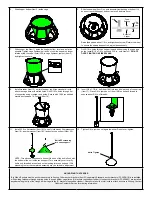
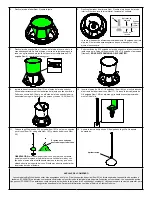
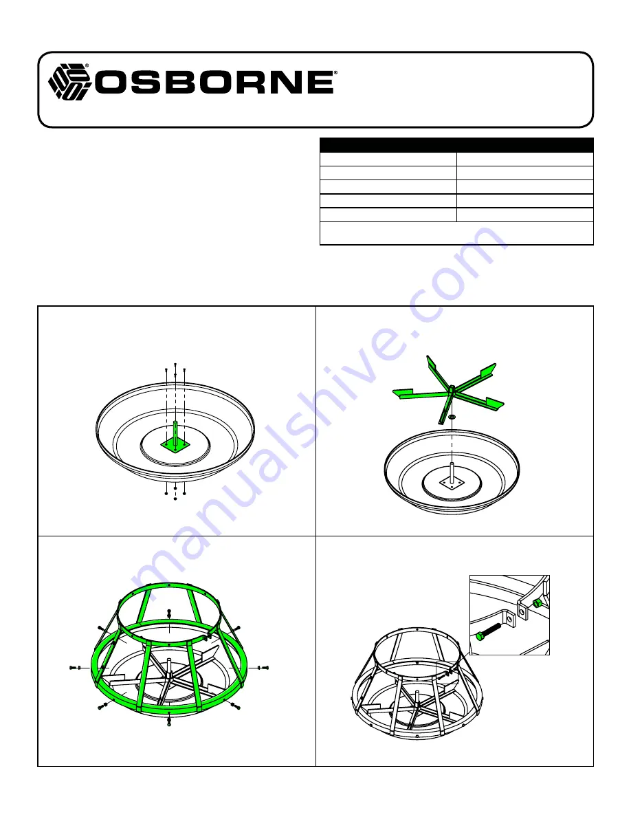
1. Install axle (Item 10) into center recess of trough (Item 12). Drill 3/16-in.
holes through trough using axle as guide. Secure using 10-24 flat head
machine screws and 10-24 nuts (Items 11 & 13).
2. Place 3/4-in. feed wheel washer (Item 9) on axle followed by feed wheel
(Item 8). If wheel does not turn freely, check for and remove paint or
galvanizing residue.
3. Force trough divider cage (Item 6) onto trough using rubber mallet.
Ensure no gaps exist between cage and trough as fiberglass could break
when bolts are installed.
Drill 5/16-in. holes through trough using cage as a guide. Install 5/16
x 7/8-in. bolts and 5/16-in. nuts (Items 7).
DO NOT OVER-TIGHTEN
BOLTS ON FIBERGLASS.
4. Attach 5/16 x 1 3/4-in. cage tightener bolt and 5/16-in. hex nut (Items 4)
into top of cage divider but do not tighten.
RLX-0526_J
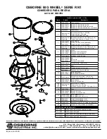
RN1 SERIES
NURSERY CONFINEMENT FEEDER
Assembly & Operating Instructions
Big Wheel
®
Hog Feeders
Required Tools
cordless drill
3/16-in. drill bit
5/16-in. drill bit
1/2-in. wrench
3/8-in. wrench
9/16-in. wrench
1/2-in. socket wrench
screwdriver
pliers
rubber mallet
NOTE:
Standard drill bits rapidly become dull when used on fiberglass. Ma
-
sonry bits are recommended. Use thread-locker on all bolts.
ASSEMBLY AND OPERATING INSTRUCTIONS:


