1 |
P a g e
FutureNow FNIP-6x2AD
Installation and Operation Manual
rev 28.04.2020
6 Channel Smart Dimmer with Local Inputs
/DIN Rail and Surface mountable/
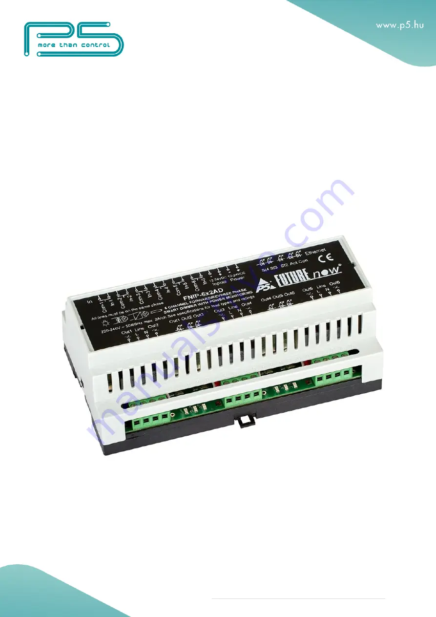
The FNIP-6x2AD dimmer
Page 1: ...1 P a g e FutureNow FNIP 6x2AD Installation and Operation Manual rev 28 04 2020 6 Channel Smart Dimmer with Local Inputs DIN Rail and Surface mountable The FNIP 6x2AD dimmer...
Page 2: ...10 CONFIGURATION 11 Configuration via the web interface 11 Connecting to the web server of the module 11 Network settings 12 Users and user rights 14 Channel settings 15 Dim settings 16 Combining cha...
Page 3: ...uency power consumption metering 100 dim levels 800 level hardware resolution Preset dim level outputs will go to the specified level when turned on Dim level memory if preset dim level is set to zero...
Page 4: ...stallation This equipment shall be installed in a closed cabinet with no access to live parts Only the top enclosure of the equipment where the label is affixed is allowed to be accessed by the operat...
Page 5: ...tput 2 Live 30 Input 2 12 Output 3 Live 31 Inputs Common 13 230V Mains input Live for ch3 and ch4 32 Input 3 14 Neutral INPUT 33 Inputs Common 15 Output 4 Live 34 Input 4 22 Output 5 Live 35 Inputs Co...
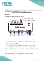
Page 6: ...isted pair CAT5 or better Outputs According to the loads attached to the outputs current and voltage Inputs A pair of low or high voltage cables The inputs use low voltage signals Mains line voltage w...
Page 7: ...breaker Different phase connection would create a short circuit and damage the module Live on terminal 3 powers output 1 and output 2 live on terminal 13 powers output 3 and output 4 live on terminal...
Page 8: ...contacts pushbuttons momentary switches relay contacts etc or open collector transistor outputs across the appropriate input terminals and the input common terminal Voltage for the inputs is supplied...
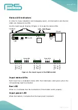
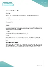
Page 9: ...ED that illuminates solid green when the corresponding input is activated Run LED When on it indicates that the Central Unit of the module works properly Input power LED When illuminated it indicates...
Page 10: ...and in the second phase of firmware updates AC LED Indicates the presence of the 50 60Hz line voltage Er LED The Er LED turns on if the module gets overheated This LED will not turn off until the mod...
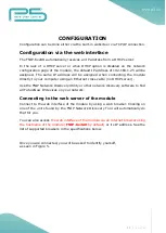
Page 11: ...ng an Ethernet cross cable no DHCP server Use the FNIP Network Discovery Utility or other network discovery software to find all FutureNow IP devices on your network Connecting to the web server of th...
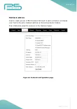
Page 12: ...k the Network tab The network configuration page is shown in Figure 6 You can choose between using DHCP or static IP address here Enable HTTP authentication HTTP authentication can be disabled to make...
Page 13: ...create groups of FNIP modules that react to scene activation commands only if set to the same multicast address as the scene activator module More information about the scenes is in the Scenes chapter...
Page 14: ...and changing all the settings Actors are allowed to control the outputs and monitor the status of the inputs and the outputs but are not allowed to change any settings Observers are allowed to monitor...
Page 15: ...nnel page As a general rule leading edge dimming can be used with resistive and inductive loads while capacitive loads require trailing edge dimming If you are not sure which mode to set click on Dete...
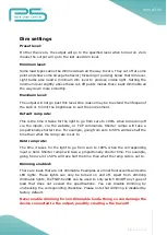
Page 16: ...via the inputs via the website or TCP commands Shorter ramps will take a proportionally shorter time For example going from zero to 50 will take half the time than what the ramp rate is set to Hold ra...
Page 17: ...ined pairs will be tied together they will always be at the same dim level but they are separate hardware outputs with different loads connected to them Hardware and software combination Besides softw...
Page 18: ...e defined state Any module in the group can send and receive this command SAC can be triggered by an input change on this module or on any module in the group Each module in the group must have the sa...
Page 19: ...m the website of P5 Then click Upload The St LED turns on and stays on or blinks during firmware update After uploading the new firmware which takes about a minute the module will automatically restar...
Page 20: ...ach short button press toggles the corresponding output Holding the button for less than 0 5s will dim up and down always in the opposite direction then last time the output until the button is let go...
Page 21: ...This mode makes it possible to use maintained standard light switches instead of momentary switches on the inputs Each trigger of the switch On or Off will toggle the outputs Please note that the pos...
Page 22: ...ng the slider will dim the outputs A grey status icon means that the output is off An active output is indicated by a red icon The current power usage is displayed for each channel A common temperatur...
Page 23: ...is displayed on the Input status page A grey icon means that the corresponding input is inactive input circuit open An active input input circuit closed is indicated by a green icon The Input Status p...
Page 24: ...socket connections whenever the status of an input or output changes The TCP IP communication can be enabled disabled via the Network settings page Most third party automation controllers that can im...
Page 25: ...at conform to EMC emission standards For example some LED drivers can generate spikes that can damage the dimmer All channels combined max 3000W in case of all output load is incandescent The above ra...
Page 26: ...perating temperature 0 C 40 C 32 104 F Dimensions W x H x D 157mm x 86mm x 57mm 9 DIN unit width Weight 0 48 kg Color Light grey with black cover plate Standards EN 60669 2 1 RoHS Test methods EN 5501...