background image


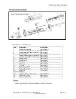
Operation and Maintenance Manual for the 

SX-90 & SX-80 Sodr-X-Tractor Handpieces 


5050-0492 Rev F 


Part Number 

Model 

Features 

6010-0106-P1 

SX-80/90 (Black connector) 

Handpiece Only 

6010-0149-P1 

SX-90 (Blue Connector) 

Handpiece Only 

6993-0213-P1 

SX-80/90 (Black connector) 

Handpiece & Cubby 

6993-0266-P1 

SX-90 (Blue Connector) 

Handpiece & Cubby 


PACE SX-90 

(Shown) 

Summary of Contents for Sodr-X-Tractor SX-80

Page 1: ...pieces 5050 0492 Rev F Part Number Model Features 6010 0106 P1 SX 80 90 Black connector Handpiece Only 6010 0149 P1 SX 90 Blue Connector Handpiece Only 6993 0213 P1 SX 80 90 Black connector Handpiece...

Page 2: ...ndpiece Setup 4 Vacuum Hose Connection 4 Tip Selection 5 Tip Installation 5 Temperature Setting 6 Burn In Procedure 6 Tip Preparation 6 Through Hole Solder Extraction 7 Tip Cleaning 7 Special Applicat...

Page 3: ...use and manipulation in tight places The Sodr X Tractor is a member of the PACE SensaTemp family of advancedhandpieces CAUTION Always return heated handpieces to the appropriate Tip Tool Stand when no...

Page 4: ...65 you may wish to leave the air hose assembly unattached to allow a quick change to any air handpiecebeing used 2 Prepare a VisiFilter in the following manner a Connect a 1 inch 2 5cm length of clear...

Page 5: ...high mass boards 2 Precision These tip feature smaller ID sizes with larger mass for improved thermal recovery 3 Flo D Sodr Tips These tips provide rapid continuous extraction of old orexcesssolderfro...

Page 6: ...o PACE system Power Source 4 Set Handpiece Tip temperature to 316 C 600 F Burn Handpiece in for 10 minutes at this temperature 5 Set Handpiece Tip Temperature to 427 C 800 F Heater Assembly will again...

Page 7: ...e complete solder melt should be 2 5seconds under normal conditions Heavymultilayerboardsmayrequire somewhatlongerheating times In extreme cases preheating or auxiliary heating is recommendedtoachiev...

Page 8: ...mbly can now be removed by simply gripping the door near the ear shaped protrusions and lifting straight up 2 Replace the disposable chamber by holding the door assembly in the palm of your hand with...

Page 9: ...on the handle assembly and gently push into place 7 Replace and tighten the two heater assembly screws Insuring that the heater assembly is snugly in place when through Be careful not to over tighten...

Page 10: ...ector Heater Assembly Blue Connector 6010 0107 P1 6010 0163 P1 5 Plunger Shaft 1261 0154 P1 6 Plunger Lock 1500 0063 P1 7 Front Seal 1213 0087 P1 8 Rear Seal 1213 0086 P1 9 C Clips 1348 0387 P3 10 Spr...

Page 11: ...ing are registered trademarks and or service marks of PACE Incorporated Annapolis Junction Maryland U S A ARM EVAC FLO D SODR MINIWAVE PACE SENSATEMP SNAP VAC SODRTEK SODR X TRACTOR THERMOFLO THERMOJE...

Reviews: