INSTALLER:
Leave this manual with the appliance.
CONSUMER:
Retain this manual for future reference.
180516-36
5055.MR30-A
WARNING: If the information in these
instructions is not followed exactly a fire or
explosion may result causing property
damage, personal injury or death.
FOR YOUR SAFETY
Do not store or use gasoline or other
flammable vapours and liquids in the vicinity
of this or any other appliance.
WHAT TO DO IF YOU SMELL GAS
•
Do not try to light any appliance.
•
Do not touch any electrical switch.
•
Do not use any phone in your building.
•
Immediately call your gas supplier
from a neighbour’s phone. Follow the
gas supplier’s instructions.
•
If you cannot reach your gas supplier
call the fire department.
Installation and service must be performed
by a qualified installer, service agency or the
gas supplier.
This appliance may be installed in an
aftermarket permanently located,
manufacture home (USA only) or mobile
home, where not prohibited by local codes.
This appliance is only for use with the type of
gas indicated on the rating plate. This
appliance is not convertible for use with
other gases unless a certified kit is used.
This appliance is suitable for installation in a
bedroom or bed sitting room.
SERIAL #
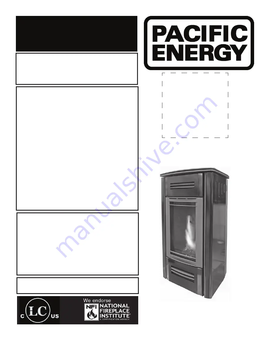
MIRAGE 30
INSTALLATION AND
OPERATING INSTRUCTIONS
MODEL: MIRAGE 30, SERIES: A
DIRECT VENT FREE STANDING
GAS STOVE
MR30
Visit www. pacificenergy.net for the most up-to-date version of this manual
Summary of Contents for MIRAGE 30 SERIES A
Page 33: ...33 180516 36 5055 MR30 A ...
Page 34: ...34 5055 MR30 A 180516 36 ...
Page 35: ...35 180516 36 5055 MR30 A ...