background image


ILK 

INSTALLATION MANUAL 

& CHECK-OFF SHEET 


ECN-M1508 Rev. 1.6, Date 09-21-20  Part #90-0413-200 


PALFINGER Liftgates, LLC. 15939 Piuma Ave., Cerritos, CA 90703   

 Tel (888)-774-5844    Fax (562)-924-8318 


PALFINGER Liftgates, LLC. 572 Whitehead Road, Trenton, NJ 08619      

Tel (609)-587-4200    Fax (609)-587-4201


Visit our website 

at 

www.palfinger.com

 for

 up to date information and notifications 

If you received this product with damaged or missing parts,  

Please contact PALFINGER Liftgates at (888)-774-5844 


Summary of Contents for ILK 22

Page 1: ...itos CA 90703 Tel 888 774 5844 Fax 562 924 8318 PALFINGER Liftgates LLC 572 Whitehead Road Trenton NJ 08619 Tel 609 587 4200 Fax 609 587 4201 Visit our website at www palfinger com for up to date information and notifications If you received this product with damaged or missing parts Please contact PALFINGER Liftgates at 888 774 5844 ...

Page 2: ...fixture 16 5 3 Bolt On Mount Plate Installation ILK 22 33 44 55 19 5 3 1 Mount Plate Installation 20 5 4 Platform Installation 23 5 4 1 Attach platform to liftarm 23 5 4 2 Installation and Adjusting the tilt cylinders 23 5 5 Installation without mount fixture 25 5 6 Setting and Operation of B 15 Sensor 26 5 7 Setting and Operation of B 13 Sensor 27 5 8 Installation of left and right Up Stops 28 5 ...

Page 3: ...on instructions Section 5 3 Recommended Tools for Installation Metric Wrench Set Basic Screwdrivers Pliers Wire Crimp Pliers Test Light Snap Ring Pliers Hammer Metric Allen Set 1 5mm 10mm Impact Sockets Sm Metric Socket Set Assorted Drill Bits Floor Jack or Equiv Sm To Med Bottle Jack Forklift or O H Crane Hand Held Grinder Paint Gun Pry Bar 3 8 Drill Motor Heat Gun or Equiv Min 250 Amp Welder Cut...

Page 4: ... 10 Do not paint cylinder shafts or nylon rollers Use non chlorinated brake cleaner to remove over spray 11 Verify that pin lock bolts are tight 12 Grease all pivot points 13 Verify that ALL decals are placed properly Contact PALFINGER Liftgates replace any missing de cals 14 Final Check Off Sheet at rear of this manual MUST be filled out and kept in your records for future reference 15 Refer to o...

Page 5: ...ter than what s allowed the sill has to be notched and capped to achieve original strength Bend flat stock and weld 100 around the notch Warning Minimum bed height dimensions are ALWAYS MAXIMUM LOADED TRUCK Floor Height Ranges Max Unloaded Truck Min Loaded Installing a gate at or close to minimum bed height normally results in a gate that will NOT open and close from stored position if the minimum...

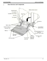
Page 6: ...t Arm Lift Cylinder Platform Warning Lights Center of Gravity of maximum load Cart Stops optional Foot control optional Platform sensor B15 under the platform Rear bumper Hydraulic Power Unit on slide tray inside the mount frame Lift arm sensor B13 Serial Tag Control box Circuit Board behind cover Gate Overview and Components ...

Page 7: ...ILK 22 33 44 55 66 INSTALLATION MANUAL Revision 1 6 7 NOTES ...

Page 8: ...______ L Frame Height Height of chassis frame ________ Truck Information Truck Dimensions Type of Body check applicable Van Flatbed Reefer Other specify ____________ Type of Rear Door check applicable Flip Up Roll Up Swing Other specify ________________ Truck Specifications Manufacturer ex Hino GVWR ex 68 000 lbs Length ex 53ft Width 96 102 Truck Chassis Dimension Sheet Liftgates Information Model...

Page 9: ...r of the trailer slider holes ________ X Eyebrow depth ________ Z Top of floor where the liftgate platform will meet the top of the eyebrow ________ Customer Information Quote SO ____________________________________________________ Company ______________________________________________________ Phone _________________________________________________________ Email _________________________ _________...

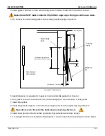
Page 10: ...d height 49 5 Min bed height 30 F dim Min 13 Max 24 F dim Kdim 700 mm 27 5 24 23 22 21 20 19 18 17 16 15 14 13 25 26 27 28 29 30 31 32 33 34 35 K dim Min 25 Max 35 4 50 4 50 4 25 4 25 4 00 4 00 3 75 3 75 3 50 3 50 3 25 S dim 11 S dim 38 7 When the K Dim is MAX the F Dim is MIN Figure 3 1 ILK22 and ILK33 Installation table Part number for ILK 22 Mounting Fixture 1 00015 Part number for ILK 33 Mount...

Page 11: ...d height 56 Min bed height 36 F dim Min 18 Max 28 F dim Kdim 28 26 24 23 22 21 20 19 18 29 30 31 32 33 34 35 36 37 K dim Min 25 Max 35 800 mm31 5 arm WhentheK dimismaxtheF dimisthemin 5 25 5 00 4 75 4 50 4 25 4 25 4 00 4 00 S dim 7 10 S dim 49 Figure 3 2 ILK33 ILK44 ILK55 installation table Part number for ILK 33 Mounting Fixture 1 00016 for ILK 44 and ILK 55 Mounting Fixture 1 00017 MINIMUM bed h...

Page 12: ...nd clearance 11 5 Ground clearance bed height Fdim 7 5 Max bed height 60 Min bed height 40 F dim Min 21 Max 31 F dim Kdim 31 29 27 26 25 24 23 22 21 32 33 34 35 36 37 38 39 40 41 42 K dim Min 32 Max 42 900 mm35 5 arm WhentheK dimismaxtheF dimisthemin 5 25 5 00 4 75 4 50 4 25 4 25 4 00 4 00 S dim 7 5 10 S dim 49 Figure 3 3 ILK66 installation table Part number for ILK 66 Mounting Fixture 1 00018 MIN...

Page 13: ...ial applications 4 1 Flip Up door Full door seal kit installation 1 Install x 1 1 2 HR flat bar to the lower rear body seal Figure 4 1 Full door seal kit 2 Install gate per instructions per 5 1 Rear Lower Body Sill 1 2 x 1 1 2 HR Flat TIRE TIRE Gasket Channel Gasket Channel Full Door Kit Only ...

Page 14: ...g header at edge of platform Figure 4 2 Flip up door 5 Apply Silaprene or equivalent to gasket channel and slide gasket into channel 6 Trim gasket flush with channel and crimp channel slightly at top and bottom to lock gasket 7 Install flip up door 8 Verify Hinge Seal is approx 3 16 above top hinge and even before tightening any fasteners Open door several times before tightening any top hinge fas...

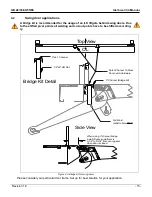
Page 15: ...ve to be shifted according ly 3 Channel Bridge Kit Notch Channel To Clear Door Latch Hardware Top View Side View Full Weld Weld to Arm ONLY Bridge Kit Detail 1 2 x2 HR Flat 3 x4 1 Channel When using 3 channel bridge install liftgate so platform is 3 1 2 to 3 3 4 from door gasket when door is closed CL Figure 4 3 Bridge kit for swing doors Please consider your particular door frame Set up for best ...

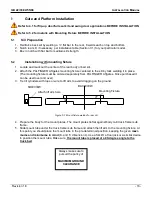
Page 16: ...elding it in place The mounting fixture must be ordered separately from PALFINGER Liftgates Once purchased it can be used over and over 3 Tie tilt cylinders with rope or wire to lift arm to avoid dragging on the ground Figure 5 1 Mount fixture welded to rear sill 4 Prepare the body for the mount plates The mount plates lie flat against body rail truck frame sub frame 5 Slide mount tube under the t...

Page 17: ...ressure on each lift arm pin This is very important to make platform align with truck sill Be certain to pull out power tray before welding IMPORTANT 8 The reservoir is made of plastic and you will burn it while welding To pull out tray open curb side mount tube rubber cover simply remove the clamp and the tray holding bolt and detach the ground strap and control power connector for the tray Pull ...

Page 18: ...Use a min of 8 overlap between mount plates and truck frame Weld 100 with 1 4 weld against the frame also weld inside and ouside of the plates against the mount frame Install Lower Gusset Supplied ON 5500 and 6600LB Units ONLY 8 overlap Before running the unit through its cycle make sure that the In Cab Switch is in the ON position lights on Before running the unit through its cycle make sure that...

Page 19: ...t plates on a C Chassis use the following amount of bolts listed below along with their torque specificaitons Model No of Bolts Bolt Type Torque Specification ILK 18 4 14 x 1 5 St 10 9 140 ft lbs 140 Nm ILK 22 4 ILQ 22 4 ILK 33 6 ILK 44 55 10 ILK 66 14 Before If it is necessary to perform any welding make sure to slide out the power pack out of the mount tube to prevent any damage to the oil tank ...

Page 20: ...1 with Hex head bolts 3 lock washer 4 and 5 square washer 3 Slide mount plates in position to frame width and slide gate under truck frame 4 Tack weld mount plates 2 to frame when gate is in position and aligned 5 Double check position of gate centered underneath the truck 6 Tighten up hex head screws 3 to secure mount frame 1 and mount plates 2 Torque on screws 5 295 ft lbs 400 Nm 2 5 1 2 3 4 5 4...

Page 21: ... 3 to secure the mount plate 2 to the mount frame U section 6 3 Align the two mount plates according to chassis frame width and snug the M20 hex nuts 4 After the mount frame 1 is positioned correctly to the chassis torque down the rear facing M20 hex nuts 5 to 295 ft lbs 400 Nm 6 5 3 1 2 Front End of MountFrame 4 3 7 ILK 33 Mount Plate Assembly Components 1 Mount Frame 4 Mount Plate Hook 2 Mount P...

Page 22: ...plates 2 and mount frame 3 Secure mount plates 2 locking brackets 4 and mount frame brackets 3 with M14 bolts 5 and nuts 6 2 Tighten the M14 hex nuts 6 onto the M14 bolts 5 to secure the mount plate 2 to the mount frame U section 6 3 Align the two mount plates according to chassis frame width and snug the M20 hex nuts 7 4 After the mount frame 1 is positioned correctly to the chassis torque the re...

Page 23: ...pins 6 Tighten up pin lock bolts 5 4 2 Installation and Adjusting the tilt cylinders Pin only one cylinder at a time to the platform 1 Tilt platform up to a point of easy access of the tilt bushings using the forklift overhead crane etc 2 When installing the tilt cylinder into the platform extend the tilting cylinder by pressing the switch for opening and closing until the pins fit in the tilt cyl...

Page 24: ...ht lock nut at tilt piston to keep Round side of tilt cylinder clevis MUST face down towards ground If you have not finished the welding carefully run lift to see if it is properly aligned with the floor sill remove pump motor from tube and finish all welding work before continuing with detail work Never power the lift hard against anything if you have not finished welding For Warning lights and f...

Page 25: ...uivalent with tack welds steel platform or clamps aluminum platform to assure level position of platform to body floor shown in Figure 4 3 Warning Never work or place yourself under unsupported Platform 8 Place the mount tube in the predetermined position keeping the given maximums and minimums F and K Dim in mind Use floor jack or a similar device to position the mount tube Make sure that you pla...

Page 26: ...inders are adjusted equally 3 Verify that the platform sensor B 15 is set correctly by placing platform in stored position fully verti cal and check that warning lights are off with cab switch off If lights still on when gate is stored loosen the 5mm x 50mm Allen Head mount screws at sensor and rotate slightly until lights turn off Retighten screws Figure 5 4 B 15 Sensor and warning light cable in...

Page 27: ...or slightly forward or back to achieve proper Auto Tilt action Lift Arm Lift Cylinder B 13 Sensor Tilt Cylinder At NO time should the platform tilt towards ground while lowering Platform should ONLY tilt AFTER Lift Arms Nylon Rollers contact ground 5 After sensor is properly set tighten lock bolt to 43 in lbs 3 5 ft lbs 6 Cycle platform several times to check operation after tightening 7 If Platfo...

Page 28: ...nd there is a slight gap approx 1 8 between lift arm and rear sill 2 Determine type of up stop for your installation 3 Set up stop so that it makes contact with liftarm 4 Tack weld in place 5 Cycle gate to verify liftarm makes contact with left and right up stops before making contact with rear sill 6 There is not an excess gap between rear sill and liftarm 7 Platform is level with body floor Inst...

Page 29: ...e power pack pulled out and hoses and cables are away from walls when welding the tube Protect all wires from dropping slag or splatter when welding mount plates 1 Verify the platform is in the correct position in relation to truck sill 2 Weld tube and mount plates and lower gusset on 5500 and 6600 lb models with a 1 4 fillet weld 100 of the area around mount tube and around frame on both sides of...

Page 30: ...e contact with other wiring brake fuel or air lines etc or get pinched against other objects 4 Heat shrink lug connection to cable 5 Assure all connections are tight and securely fastened Main Batteries 2GA Liftgate Power Cable Resetable Circuit Breaker Ground In Line Fuse Wires 2 and 4 go to postitive Wires 1 and Gr Yl go to ground In Line ATC Fuse 20 Amp Replace with same amperage fuse when nece...

Page 31: ...e amperage breaker when necessary Ground For optimal grounding ground all batteries and power units to the body side rails of the vehicle NOTICE DO NOT attempt to jump in line fuses with other objects other than the specified fuse Do not increase the amperage rating of fuse Serious harm to the liftgate will result when standard practices are not followed Ground Trailer Wiring Diagram Never secure ...

Page 32: ...un only the cab switch into the cab Battery cable and 4 wire control power cable will go di rectly to the truck battery 2 and 4 go to positive post with an inline 20 amp fuse 1 and green yellow go to negative post 3 Install the supplied breaker to the positive terminal of the battery using copper buss ban 4 Mount circuit breaker securely on top of battery 5 Connect 2Ga Cable from liftgate to the c...

Page 33: ...Cut Off Switch for Trailer Application 6 2 Place cab shut off in view of the driver and within reach from the ground Recommended Cable Routing for Trucks Body Stringer Sub Wood Truck Frame Cable Staples Route Cables to OUTSIDE of U Bolts For trailer installation refer to trailer manufacturers recommended routing Battery Cable 2 Wire Control Box Power Cable 4 Wire Control Cable No Use Blue 4 Black ...

Page 34: ...rtain the platform is clear before operating the lift Liftgate shut off switch must be turned off when liftgate is not in use Keep platform in horizontal position when loading and unloading Always raise the platform to floor level in horizontal position before closing Do not overload refer to capacity decals Tilt Lift Max Capacity on Platform Platform 24 Up Down Up Down Load OPERATING INSTRUCTIONS...

Page 35: ...irst add the 2 1 heat shrink over one of the harnesses Second use the butt splice heat shrink connectors provided Crimp the corresponding wires from each harness together as shown per wire number Apply heat to each individual butt connector to seal Finally slide the 2 1 heat shrink over the spliced wire and seal 3 Test each function to verify the control is functioning as intended Use the provided...

Page 36: ...Socket Plug Connectors Power LED Wiring Socket Connection Rear View Hand Held Remote 5 2 Up 4 3 2 Tilt Up 1 14 2 Tilt Down 2 6 2 Down 3 4 Hot Green Yellow Socket Plug Control Board 5 2 Up Yellow 3 2 Tilt Up White 14 2 Tilt Down Green 6 2 Down Brown 4 3 Hot Red Wiring Plug Connection Rear View Key Key ...

Page 37: ...er LED Wiring Socket Connection Rear View Hand Held Remote 6 2 Down 3 4 Hot Green Yellow 5 2 Up 4 3 2 Tilt Up 1 14 2 Tilt Down 2 Socket Plug Control Board Wiring Plug Connection Rear View Not in Use 6 2 Down Brown 14 2 Tilt Down Green 3 2 Tilt Up White 5 2 Up Yellow 4 3 Hot Red Not in Use ...

Page 38: ...ontrol Board Hand Held Remote Wiring Socket Connection Rear View 6 2 Down 3 4 Hot Green Yellow 5 2 Up 4 3 2 Tilt Up 1 14 2 Tilt Down 2 Wiring Plug Connection Rear View Not in Use 1 2 3 4 6 7 5 6 2 Down 3 4 3 Hot Red 14 2 Tilt Down Green 3 2 Tilt Up 1 5 2 Up Yellow Not in Use 1 6 5 4 2 7 3 plus ...

Page 39: ...to port 5 on J3 switch 2 connects to port 6 on J3 Make sure that connections are wire tied together and pushed in side the platform DOWN Step on switch 1 and hold wait between one and three seconds before you step on switch 2 UP Step on switch 2 and hold wait between one and three seconds before you step on switch 1 If platform tip is tilted to ground platform will tilt up to preset position befor...

Page 40: ...age is the most important first step in troubleshooting the litgate Test voltage at the J11connection between wire 4 and ground min 10 V When testing for electricity on the individual solenoid plug at the cylinder always test voltage between the two prongs on the plug itself min 7 V After troubleshooting carefully close the rubber cap and secure it with the plastic strap CLOSE LOWER LIFT HACKBARTH...

Page 41: ... Diagnosis mode activated Defect at motor solenoid detected during lifting Voltage V02 J1 pin 2 is missing defective fuse Defect at opening valve S3 S4 or motor relay detected during opening S5 valve detected during closing or motor solenoid defective S5 valve detected or defect at lowering valve S1 S2 Cab switch off on or disconnect bridge J11 2 4 Automatically when the valves are back to normal ...

Page 42: ...ing function S3 and S4 Release Valve for tilt down function R1 and R2 Flow Restrictor located inside hose adaptor on lift cylinder R3 and R4 Flow Restrictor located inside hose adaptor on tilt cylinder S5 Shift Valve is activated on tilt up and lowering function R5 Restrictor Valve located in power pack Flow Divider is activated when fluid is going back into the power pack If Flow Divider is loose...

Page 43: ...lock bolts for proper torque of 14 ft lbs 7 Paint all welded areas and area that have been scratched during installation Note Do not paint chrome hydraulic piston rods 8 Remove any overspray from cylinder piston rods 9 Check for any wires or hoses that may rub during operation 10 Re route and or tie up wires and hoses as necessary 11 Lower platform completely to ground and slide out pump motor to ...

Page 44: ...ate instructions B 1 ATG ILK Main Operation Control Box C 2 ATG XXXX Max Capacity please check the serial number plate to find out your specific capacity D 1 ATG CAB Liftgate Shut Off must be placed next to the Shut Off Switch E 1 ATG BKR Circuit Breaker Reset must be located at the circuit breaker F 2 ATG WLH Warning liftgate can crush G 2 ATG CTN Caution Always stand clear of platform area H 1 A...

Page 45: ...ecal G on the back of the platform visible from outside when platform is closed Decal J Decal K Figure 1 Decal Placement Guideline Decal D in the truck cab or at On Off at rear Decal E by circuit breaker at batteries Decal L On mount plates Aluminum operation plate for foot control 3 x4 P 1341966 ...

Page 46: ...without the written permission of Interlift Inc This drawing and it s contents are the the property of Interlift Inc and Drawn by Date Rev Date MH 3 03 09 Liftgate Mounting Fixture 56 Model A B ILK 22 ILK 33 ILK 44 55 C D 44 3 4 53 1 4 53 1 1 2 1 3 8 1 15 16 1 1 4 1 7 16 Correct Placement ILK 22 33 44 55 66 A Inside Dimension 3 x3 x1 4 Angle 7 8 1 1 4 1 5 16 ILK 66 ...

Page 47: ...linder shafts 3 Cylinders FINAL 1 Platform Touches Ground WELDS 1 Full Welds Mount Plates INSPECTION 2 Lights Working On Chassis 2 Ground Off Clean 3 Lic Plate Bolts Lights 3 Frame Capped Off 4 Decals Installed 5 Rubber Plastic Caps on 6 Gate Painted Completely 7 Body Clean Around Gate PUMP 1 Check Fluid With Platform On Ground 8 Pin Greased 12 Places MOTOR 2 Connections Tight With Heat Shrink 9 C...

Reviews: