background image

ION 1200 Hardware Reference

docs.paloaltonetworks.com

Summary of Contents for ION 1200 Series

Page 1: ...ION 1200 Hardware Reference docs paloaltonetworks com ...

Page 2: ... paloaltonetworks com search html Have feedback or questions for us Leave a comment on any page in the portal or write to us at documentation paloaltonetworks com Copyright Palo Alto Networks Inc www paloaltonetworks com 2021 2022 Palo Alto Networks Inc Palo Alto Networks is a registered trademark of Palo Alto Networks A list of our trademarks can be found at www paloaltonetworks com company trade...

Page 3: ...l 39 ION 1200 S C5G WW Front Panel 41 ION 1200 S Back Panel 43 ION 1200 S C NA ROW Back Panel 44 ION 1200 S C 5G Back Panel 45 ION 1200 LEDs 46 ION 1200 S Compliance Statement 48 Installation Kit Components 50 Install the ION 1200 51 Install Antennas 52 Insert SIM Cards 54 Install the ION 1200 on a Flat Surface 58 Install the ION 1200 on a Wall 59 Wall Mount Template 63 Install the ION 1200 in a 1...

Page 4: ... 1200 S 75 Install the ION 1200 S on a wall 77 ION 1200 S Wall Mount Template 80 Install the ION 1200 S on a Rack 81 Troubleshoot ION 1200 87 Troubleshoot Common Issues with the ION 1200 88 ION 1200 Hardware Reference 4 2022 Palo Alto Networks Inc ...

Page 5: ...Before You Begin Tamper Proof Statement Third Party Component Support Product Safety Warnings 5 ...

Page 6: ...uct The tracking number provided to you electronically when ordering the product matches the tracking number that is physically labeled on the box or crate The integrity of the tamper proof tape used to seal the box or crate is not compromised The integrity of the warranty label on the firewall or appliance is not compromised ION 1200 Hardware Reference 6 2022 Palo Alto Networks Inc ...

Page 7: ...Begin Third Party Component Support Before you consider installing third party hardware read the Palo Alto Networks Third Party Component Support statement ION 1200 Hardware Reference 7 2022 Palo Alto Networks Inc ...

Page 8: ...autre extrémité du bracelet est raccordée à la terre Use grounded and shielded Ethernet cables to ensure agency compliance with electromagnetic compliance EMC regulations French Translation Des câbles Ethernet blindés reliés à la terre doivent être utilisés pour garantir la conformité de l organisme aux émissions électromagnétiques CEM I O ports are intended for intra building connections only and...

Page 9: ...pliance with the FCC guidelines for Human Exposure to Radio Frequency Electromagnetic Fields FCC Bulletin 65C 01 01 Evaluating Compliance with the FCC guidelines for Human Exposure to Radio Frequency Electromagnetic Fields Additional Information for Evaluating Compliance for Mobile and Portable Devices with FCC limits for Human Exposure to Radio Frequency Emission World Health Organization Interna...

Page 10: ... that may cause undesired operation of the device French Translation L émetteur récepteur exempt de licence contenu dans le présent appareil est conforme aux CNR d Innovation Sciences et Développement économique Canada applicables aux appareils radio exempts de licence L exploitation est autorisée aux deux conditions suivantes L appareil ne doit pas produire de brouillage L appareil doit accepter ...

Page 11: ...l The use of software or firmware not supported provided by the manufacturer may result in the equipment being no longer compliant with the regulatory requirements Australia and New Zealand To ensure compliance with RF exposure standards the system must only be operated with Palo Alto Networks approved antennas and accessories To ensure compliance with exposure limits to radio frequency fields the...

Page 12: ...Before You Begin ION 1200 Hardware Reference 12 2022 Palo Alto Networks Inc ...

Page 13: ...ION 1200 C 5G WW Front Panel ION 1200 Back Panel ION 1200 C NA ROW Back Panel ION 1200 C 5G Back Panel ION 1200 Compliance Statement ION 1200 S Front Panel ION 1200 S C NA ROW Front Panel ION 1200 S C5G WW Front Panel ION 1200 S Back Panel ION 1200 S C NA ROW Back Panel ION 1200 S C 5G Back Panel ION 1200 LEDs ION 1200 S Compliance Statement Installation Kit Components 13 ...

Page 14: ...to endpoint devices through PoE capable switch ports The variants of the ION 1200 series are ION 1200 for enterprise small branch ION 1200 C NA and ION 1200 C ROW for small branch with integrated 4G LTE for North America NA or Rest of the World ROW ION 1200 C 5G WW for small branch with integrated 5G for world wide WW ION 1200 S for enterprise small branch with integrated Layer 2 switch ports ION ...

Page 15: ... S C ROW ION 1200 S C NA Enterprise small branch with integrated Layer 2 switch ports and 4G LTE for North America NA ION 1200 S C ROW Enterprise small branch with integrated Layer 2 switch ports and 4G LTE for APAC and EMEA Rest of the World ION 1200 S C5G WW Enterprise small branch with integrated Layer 2 switch ports and 5G for world wide WW ION 1200 Hardware Reference 15 2022 Palo Alto Network...

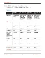
Page 16: ...RJ 45 1 x RJ 45 1 x RJ 45 1 x RJ 45 WAN LAN ports 4 x 10 100 1000 RJ 45 4 x 10 100 1000 RJ 45 4 x 10 100 1000 RJ 45 4 x 10 100 1000 RJ 45 USB 2 x Type A 2 x Type A 2 x Type A 2 x Type A eMMC Storage 32GB 32GB 32GB 32GB Encrypted IP throughput measured with 1400 byte packets 250Mbps 250Mbps 250Mbps 250Mbps Memory 8GB 8GB 8GB 8GB Type or Watts 25W Power adapter 40W Power adapter 40W Power adapter 40...

Page 17: ...C 70ºC Operating humidity non condensing 10 90 10 90 10 90 10 90 Storage humidity non condensing 10 90 10 90 10 90 10 90 Physical Dimensions DxWxH 6 42 x9 53 x1 73 163mmx242mmx44mm 6 42 x9 53 x1 73 163mmx242mmx44mm 6 42 x9 53 x1 73 163mmx242mmx44mm 6 42 x9 53 x1 73 163mmx24 Weight lbs 3 69 3 75 3 75 3 75 Mount options Rack Desktop Wall Rack Desktop Wall Rack Desktop Wall Rack Desktop Wall Cellular...

Page 18: ...39 B40 B41 B42 B46 B48 B66 B71 3G B1 B2 B3 B4 B5 B6 B8 B9 B19 Cellular Carrier Certification Not Supported AT T Verizon PTCRB T Mobile GCF AT T PTCRB T Mobile Verizon GCF Learn the new hardware specifications of the ION 1200 S series ION 1200 S ION 1200 S C NA ION 1200 S C ROW ION 1200 S C5G WW Description Enterprise small branch device with L2 switch ports Enterprise small branch device with inte...

Page 19: ... budget 4xPoE ports 60W max port USB 3 0 2 x Type A ByPass Pair 2xRJ 45 1pair eMMC Storage 128GB Encrypted IP throughput measured with 600 byte packets 250Mbps Memory 8GB Type or Watts 150W Power adapter HTTP throughput Mbps Power Input AC 100 240 V 50 60Hz Mechanical System Cooling Fanless Certifications Certifications IEC 62368 1 cTUVus FCC CE B RoHS FIPS IEC 62368 1 cTUVus FCC CE B RoHS FIPS IE...

Page 20: ...non condensing 10 90 10 90 10 90 10 90 Physical Dimensions DxWxH 9 x 13 x 1 73 228 6mm x 330 2mm x 43 9mm Weight lbs 7 79 7 85 7 85 7 85 Mount options Rack Desktop Rack Desktop Rack Desktop Rack Desktop Cellular specifications SIM Slot Size Not Supported Nano 4FF Nano 4FF Nano 4FF Radio Not Supported Main TX RX1 AUX RX2 GNSS Main TX RX1 AUX RX2 GNSS Main TX1 RX1 MIMO1 TX2 RX2 MIMO2 RX3 GNSS L5 AUX...

Page 21: ...B32 B38 B40 B41 B42 B43 3G B1 B5 B8 5G NR Sub 6GHz FR1 n1 n2 n3 n5 n28 n41 n66 n71 n77 n78 n79 LTE B1 B2 B3 B4 B5 B7 B8 B12 B13 B14 B17 B18 B19 B20 B25 B26 B28 B29 B30 B32 B34 B38 B39 B40 B41 B42 B46 B48 B66 B71 3G B1 B2 B3 B4 B5 B6 B8 B9 B19 Cellular Carrier Certification Not Supported AT T Verizon PTCRB T Mobile GCF AT T PTCRB T Mobile Verizon GCF ION 1200 Hardware Reference 21 2022 Palo Alto Ne...

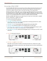
Page 22: ...B Port USB 3 0 reserved for future use 4 Console Port RJ 45 Serial console port 5 Ethernet Ports RJ 45 WAN LAN ports 6 Link Speed LED On ethernet ports 1 4 the left LED indicates the link speed 7 Activity LED On ethernet ports 1 4 the right LED indicates the activity on the port 8 Power LED Power LED the LED turns green when powered on 9 OS LED Operating System status LED ION 1200 Hardware Referen...

Page 23: ...0 Overview Item Component Description 10 Controller LED Controller LED the LED turns green on successful connection with the Prisma SD WAN controller ION 1200 Hardware Reference 23 2022 Palo Alto Networks Inc ...

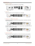
Page 24: ...ption 1 Power Power input 2 Restart Button Restart button 3 USB Port USB 3 0 reserved for future use 4 Console Port RJ 45 Serial console port 5 Ethernet Ports RJ 45 WAN LAN ports 6 Link Speed LED On ethernet ports 1 4 the left LED indicates the link speed 7 Activity LED On ethernet ports 1 4 the right LED indicates the activity on the port 8 Power LED Power LED the LED turns green when powered on ...

Page 25: ...en on successful connection with the Prisma SD WAN controller 11 Cellular LED Cellular LED the LED indicates signal strength Refer ION 1200 LEDs to know more 12 Antenna Connector Antenna SMA F Connectors ION 1200 C NA ROW has three antenna connectors Main TX RX1 Aux RX2 GNSS ION 1200 Hardware Reference 25 2022 Palo Alto Networks Inc ...

Page 26: ...1 4 the left LED indicates the link speed 7 Activity LED On ethernet ports 1 4 the right LED indicates the activity on the port 8 Power LED Power LED the LED turns green when powered on 9 OS LED Operating System status LED 10 Controller LED Controller LED the LED turns green on successful connection with the Prisma SD WAN controller 11 Cellular LED Cellular LED the LED indicates signal strength Re...

Page 27: ...ION 1200 Overview Item Component Description MIMO1 TX2 RX2 MIMO2 RX3 GNSS L5 AUX RX4 GNSS L1 ION 1200 Hardware Reference 27 2022 Palo Alto Networks Inc ...

Page 28: ...onents Item Component Description 1 Serial Number Serial number of the ION device 2 Earthing Earth ground connection The ground connector is not required during normal operation 3 Part Number Part number of the ION device 3 QR Code QR code links to the ION 1200 Hardware Reference ION 1200 Hardware Reference 28 2022 Palo Alto Networks Inc ...

Page 29: ...OW and the table describes the back panel components Item Component Description 1 and 11 Antenna Connectors Antenna SMA F connectors 2 Serial Number Serial number of the ION device 3 Earthing Earth ground connection The ground connector is not required during normal operation 4 Part Number Part number of the ION device 5 IMEI Label IMEI number of the device ION 1200 Hardware Reference 29 2022 Palo...

Page 30: ...IM slots 7 SIM slots 2 SIM slots for cellular network connectivity 8 QR Code QR code links to the SIM installation section of the Hardware Reference 9 Screws M3 screws 10 QR Code QR code links to the ION 1200 Hardware Reference ION 1200 Hardware Reference 30 2022 Palo Alto Networks Inc ...

Page 31: ...nector Antenna SMA F connectors 2 Serial Number Serial number of the ION device 3 Earthing Earth ground connection The ground connector is not required during normal operation 4 Part Number Part Number of the ION device 5 IMEI Label IMEI number of the device 6 SIM Cover SIM cover that covers the SIM slots 7 SIM slots 2 SIM slots for cellular network connectivity ION 1200 Hardware Reference 31 2022...

Page 32: ...t Description 8 QR Code QR code links to the SIM installation section of the Hardware Reference 9 Screws M3 screws 10 QR Code QR code links to the ION 1200 Hardware Reference ION 1200 Hardware Reference 32 2022 Palo Alto Networks Inc ...

Page 33: ...d to take corrective actions KCC Translation Korean Communications Commission KCC Class B Statement This equipment is an electromagnetic compatible device for business purposes Class B The provider or user should be aware that the equipment is intended for use outside the home UL Product Ambient Temperature 0 50 degree C Risk of explosion if battery is replaced by an incorrect type Dispose of used...

Page 34: ...00 C ROW Federal Communications Commission FCC statement for a Class B digital device or peripheral This equipment has been tested and found to comply with the limits for a Class B digital device pursuant to Part 15 of the FCC Rules These limits are designed to provide reasonable protection against harmful interference in a residential installation This equipment generates uses and can radiate rad...

Page 35: ...Statement ICES Canadian EMC Compliance Statement This Class B digital apparatus complies with Canadian ICES 003 French Translation Cet appareil numérique de la classe B est conforme à la norme NMB 003 du Canada ION 1200 Hardware Reference 35 2022 Palo Alto Networks Inc ...

Page 36: ...nd For use in Mexico operation of this equipment is subject to the following conditions This equipment or device may not cause harmful interference This equipment or device must accept any interference including interference may cause its undesired operation ION 1200 Hardware Reference 36 2022 Palo Alto Networks Inc ...

Page 37: ...rs ByPass is indicated with a orange bar above and below the ports 6 Ethernet Ports Ports 5 10 are access ports Ports 7 10 are PoE ports indicated with a yellow bar above and below the ports 7 Link Speed LED On ethernet ports 1 10 the left LED indicates the link speed 8 Activity LED On ethernet ports 1 10 the right LED indicates the activity on the port 9 Power Power Input 10 Restart button Restar...

Page 38: ...ION 1200 Overview Item Component Description 13 Power LED Power LED the LED turns green when powered on 14 Heat Label Heat label on the device ION 1200 Hardware Reference 38 2022 Palo Alto Networks Inc ...

Page 39: ... are SFP RJ 45 combo ports 5 ByPass Pair Ports 3 and 4 are bypass pairs ByPass ports are indicated with an orange bar above and below the ports 6 Ethernet Ports Ports 1 10 are access ports Ports 7 10 are PoE ports indicated with a yellow bar above and below the ports 7 Link Speed LED On ethernet ports 1 10 the left LED indicates the link speed 8 Activity LED On ethernet ports 1 10 the right LED in...

Page 40: ...sma SD WAN controller 13 OS LED Operating System status LED 14 Power LED Power LED the LED turns green when powered on 15 Antenna Connector Antenna SMA F Connectors ION 1200 S C NA ROW has three antenna connectors Main TX RX1 Aux RX2 GNSS 16 Heat Label Heat label on the device ION 1200 Hardware Reference 40 2022 Palo Alto Networks Inc ...

Page 41: ...ir Ports 3 and 4 are bypass pairs ByPass ports are indicated with an orange bar above and below the ports 6 Ethernet Ports Ports 1 10 are access ports Ports 7 10 are PoE ports indicated with a yellow bar above and below the ports 7 Link Speed LED On ethernet ports 1 4 the left LED indicates the link speed 8 Activity LED On ethernet ports 1 4 the right LED indicates the activity on the port 9 Power...

Page 42: ...roller 13 OS LED Operating System status LED 14 Power LED Power LED the LED turns green when powered on 15 Antenna Connector Antenna SMA F Connectors ION 1200 C5G WW has four antenna connectors Main TX1 RX1 MIMO1 TX2 RX2 MIMO2 RX3 GNSS L5 AUX RX4 GNSS L1 16 Heat Label Heat label on the device ION 1200 Hardware Reference 42 2022 Palo Alto Networks Inc ...

Page 43: ...mponents Item Component Description 1 Earthing Earth ground connection The ground connector is not required during normal operation 2 Serial Number Serial number of the ION device 3 Part Number Part number of the ION device 4 QR Code QR code links to the ION 1200 Hardware Reference ION 1200 Hardware Reference 43 2022 Palo Alto Networks Inc ...

Page 44: ...na SMA F connectors 2 SIM slots 2 SIM slots for cellular network connectivity 3 SIM Cover and QR Code SIM cover that covers the SIM slots and QR Code on the SIM cover 4 IMEI Label IMEI number of the device 5 Earthing Earth ground connection The ground connector is not required during normal operation 6 Serial Number Serial number of the ION device 7 Part Number Part number of the ION device 8 QR C...

Page 45: ...rk connectivity 3 SIM Cover with QR Code SIM cover that covers the SIM slots QR code links to the ION 1200 Hardware Reference 4 IMEI Label IMEI number of the device 5 Earthing Earth ground connection The ground connector is not required during normal operation 6 Serial Number Serial number of the ION device 7 Part Number Part Number of the ION device 8 QR Code QR code links to the SIM installation...

Page 46: ... to the controller Red LED indicates the device is attempting to connect to the controller Link Activity On ethernet ports the right LED displays the link activity The LED blinks when there is activity detected on the link Link Speed On ethernet ports the left LED displays the link speed on the port Off No link or speed is 10Mbps Green Link detected and speed is 100Mbps Yellow Link detected and sp...

Page 47: ... on the signal strength 25 blinks in 10 seconds Good signal strength 10 blinks in 10 seconds Fair signal strength 5 blinks in 10 seconds Poor signal strength You can also the view the signal strength on the Interface tab of the Prisma SD WAN web interface Excellent Good Fair Poor Modem Error hover over the icon to see the error No modem or signal detected ION 1200 Hardware Reference 47 2022 Palo A...

Page 48: ...lating to the LVD Directive 2014 35 EU EMC Directive 2014 30 EU WEEE Directive 2012 19 EU and RoHS Directives 2011 65 EU and 2015 863 EU ION 1200 S C ROW is in conformity with the harmonized standards and fulfills the essential requirements of the Radio Equipment Directive 2014 53 EU WEEE Directive 2012 19 EU and RoHS Directives 2011 65 EU and 2015 863 EU The full text of the EU declaration of con...

Page 49: ...ital device pursuant to Part 15 of the FCC Rules These limits are designed to provide reasonable protection against harmful interference in a residential installation This equipment generates uses and can radiate radio frequency energy and if not installed and used in accordance with the instructions may cause harmful interference to radio communications However there is no guarantee that interfer...

Page 50: ...er bracket to wood studs or plywood 6x Drywall anchors and screws 1 25 to mount the device and power adapter bracket to a drywall or similar material that cannot securely accommodate wood screws 3x Omni directional Dipole Antennas for ION 1200 C NA ION 1200 C ROW ION 1200 S C NA and ION 1200 S C ROW 4x Omni directional Dipole Antennas for ION 1200 C 5G WW and ION 1200 S C5G WW Sheet Limited Warran...

Page 51: ... to install the ION 1200 series Install Antennas Insert SIM Cards Install the ION 1200 on a Wall Install the ION 1200 on a Flat Surface Install the ION 1200 in a 19 inch Equipment Rack Install the ION 1200 Using the Racktray Power on the ION 1200 51 ...

Page 52: ...tors Feature Description Antennas Multi Band 4G 5G Antenna 4G 3x SMA Antenna connectors 5G 4x SMA Antenna connectors Frequency Range 615 960MHz 1500 1600MHz 1710 2690MHz 3300 3700MHz Peak Gain 2 3dBi in 800MHz band 4 4dBi in 1575MHz band 2 6dBi in 2170MHz band 1 7dBi in 3300MHz band 3 8dBi in 4400MHz band VSWR 3 1 Feed Impedance 50Ω Power Handling 30 dBm Interface SMA F Connectors Antenna Dimensio...

Page 53: ...he antennas to receive optimal cellular signal strength Check the signal strength on the ION device by viewing the Cellular LED signal strength indicator or on the Prisma SD WAN web interface Do not place the antennas close to or pointing to one another or layover one another Make sure the power cables do not cross over the antennas to avoid signal quality distortion and antenna performance degrad...

Page 54: ...00 C ROW and ION 1200 C 5G WW devices support two SIM slots to enable multiple mobile network connectivity STEP 1 Remove the SIM cover by unfastening the two M3 screws using a type one Phillips screwdriver ION 1200 Hardware Reference 54 2022 Palo Alto Networks Inc ...

Page 55: ...in figure below Ensure to correctly insert the SIM in the SIM slot incorrect insertion may damage the SIM By default SIM slot 1 is the primary SIM If you have only one SIM it is recommended to use the slot 1 as the primary SIM If you want to use the SIM slot 2 as the primary SIM you need to manually configure the SIM slot 2 as the primary SIM on the Prisma SD WAN web interface ION 1200 Hardware Re...

Page 56: ...Install the ION 1200 ION 1200 Hardware Reference 56 2022 Palo Alto Networks Inc ...

Page 57: ...r inserting the SIM place the SIM cover back on the device To eject the SIM from the device gently push the SIM inward using a finger tip and release it before pulling it out ION 1200 Hardware Reference 57 2022 Palo Alto Networks Inc ...

Page 58: ...1200 series ships with rubber feet attached to each corner of the device As pictured below the ION 1200 device can be horizontally situated on a flat surface You can also install the ION 1200 on a rack or a wall ION 1200 Hardware Reference 58 2022 Palo Alto Networks Inc ...

Page 59: ...l size in the Print options to ensure the screw hole markers line up correctly Ensure there are no building services water gas or wiring behind the wall where you intend to install the device STEP 2 Use a 1 Phillips head screwdriver to install the appropriate screws into each of the four marked locations Drywall Press a drywall anchor slightly into the center of a template mark Then use the screwd...

Page 60: ...ew Plywood wall Use the screwdriver to insert a 75 wood screw into the center of each template mark that is located over wood until the bottom of the screw heads protrude 1 4 6cm from the wall STEP 3 Align the four holes on the bottom of the device with the four screws on the wall and hang the device on the screws Make sure the device is securely connected to each of the four screws before you let...

Page 61: ... the notches in the bracket to prevent the power cord from falling out After you secure the power adapter to the bracket mount the bracket next to the device using wood or drywall screws as appropriate The following image shows a completed installation for an ION 1200 with a single power adapter ION 1200 Hardware Reference 61 2022 Palo Alto Networks Inc ...

Page 62: ...Install the ION 1200 ION 1200 Hardware Reference 62 2022 Palo Alto Networks Inc ...

Page 63: ...nd print the following wall mount template to secure the template to the wall where you intend to mount the ION 1200 device and use it to mark the location for each of the four wall mount screws ION 1200 Hardware Reference 63 2022 Palo Alto Networks Inc ...

Page 64: ...N 1200 device in a 19 rack The installation hardware consists of a metal base and two rails To ease installation first install the device in the racktray and then install the assembled racktray into the equipment rack Install the ION 1200 Using the Racktray ION 1200 Hardware Reference 64 2022 Palo Alto Networks Inc ...

Page 65: ...e fixed mounting brackets to create a mounting rail Repeat for the second mounting rail The adjustable and fixed brackets are the same for the left and right side STEP 2 Align the bottom edge of the mounting rails to the bottom of the 1 RU rack space reserved for the device Align the slotted holes in the adjustable mounting bracket to the holes on the rear of the equipment frame The mounting rails...

Page 66: ...P 3 Secure the rails to the equipment frame with mounting screws not provided compatible with your equipment frame Tighten the screws to their recommended torque value ION 1200 Hardware Reference 66 2022 Palo Alto Networks Inc ...

Page 67: ...200 STEP 4 With the front of the device facing forward align the four rubber feet on the bottom of the device to the slotted holes in the provided mounting tray ION 1200 Hardware Reference 67 2022 Palo Alto Networks Inc ...

Page 68: ...Install the ION 1200 STEP 5 Secure the device in place using three of the provided 6 32 x 3 16 Long Flathead screws ION 1200 Hardware Reference 68 2022 Palo Alto Networks Inc ...

Page 69: ...N 1200 STEP 6 Slide the device power supply into the marked position and fasten the provided velcro strap around the power supply until it is secure in place ION 1200 Hardware Reference 69 2022 Palo Alto Networks Inc ...

Page 70: ...wraps bind and secure the power supply cable to the metal hooks in the mounting tray STEP 8 Slide the mounting tray into the rails previously fixed to the equipment rack Stop when the front flange on the mounting tray is flush with the front of the rail ION 1200 Hardware Reference 70 2022 Palo Alto Networks Inc ...

Page 71: ... holes in the equipment frame Secure the mounting tray to the equipment frame on both sides using 3 screws each not provided The screws must be compatible with your equipment frame STEP 10 Proceed to Power on the ION 1200 ION 1200 Hardware Reference 71 2022 Palo Alto Networks Inc ...

Page 72: ...the following ways Shut down using the Device Toolkit commands Run the device toolkit command debug shutdown to shut down the device Ensure the device is physically accessible to turn it back on before executing the command Shut down using the Power Switch Press the power switch for more than five to eight seconds and then release to shut down the ION 1200 device When you shut down the device usin...

Page 73: ... explains the installation procedure for the ION 1200 s device Install Antennas in the ION 1200 S Insert SIM Cards in the ION 1200 S Install the ION 1200 S on a wall ION 1200 S Wall Mount Template Install the ION 1200 S on a Rack 73 ...

Page 74: ...n orientation into the SIM slot as shown in figure below Ensure to correctly insert the SIM in the SIM slot incorrect insertion may damage the SIM By default SIM slot 1 is the primary SIM If you have only one SIM it is recommended to use the slot 1 as the primary SIM If you want to use the SIM slot 2 as the primary SIM you need to manually configure the SIM slot 2 as the primary SIM on the Prisma ...

Page 75: ... SMA F connectors Feature Description Antennas Multi Band 4G 5G Antenna 4G 3x SMA Antenna connectors 5G 4x SMA Antenna connectors Frequency Range 615 960MHz 1500 1600MHz 1710 2690MHz 3300 3700MHz Peak Gain 2 3dBi in 800MHz band 4 4dBi in 1575MHz band 2 6dBi in 2170MHz band 1 7dBi in 3300MHz band 3 8dBi in 4400MHz band VSWR 3 1 Feed Impedance 50Ω Power Handling 30 dBm Interface SMA F Connectors Ant...

Page 76: ...ntennas to receive optimal cellular signal strength Check the signal strength on the ION device by viewing the Cellular LED signal strength indicator or on the Prisma SD WAN web interface Do not place the antennas close to or pointing to one another or layover one another Make sure the power cables do not cross over the antennas to avoid signal quality distortion and antenna performance degradatio...

Page 77: ...N 1200 S STEP 2 Use a 1 Phillips head screwdriver to install the appropriate screws into each of the four marked locations Drywall Press a drywall anchor slightly into the center of a template mark Then use the screwdriver to apply pressure while turning the anchor clockwise until the surface of the anchor is flush with the wall After the drywall anchor is secure install a 1 25 anchor screw into t...

Page 78: ...les on the bottom of the device with the four screws on the wall and hang the device on the screws Make sure the device is securely connected to each of the four screws before you let go ION 1200 Hardware Reference 78 2022 Palo Alto Networks Inc ...

Page 79: ...om falling out After you secure the power adapter to the bracket mount the bracket next to the device using wood or drywall screws as appropriate The following image shows a completed installation for an ION 1200 S with a single power adapter If you need a second power supply you need to order a power adapter and an adapter wall mount kit separately ION 1200 Hardware Reference 79 2022 Palo Alto Ne...

Page 80: ...d and print the following wall mount template to secure the template to the wall where you intend to mount the ION 1200 S device and use it to mark the location for each of the four wall mount screws ION 1200 Hardware Reference 80 2022 Palo Alto Networks Inc ...

Page 81: ...tion first install the device in the racktray and then install the assembled racktray into the equipment rack For the rack mounted devices the temperatures must not exceed a specified maximum ambient temperature of 40 degrees Celsius If there is any other heat source in the rack you may need to add some form of ventilation such as fans or thermal pads to prevent internal thermal buildup Maintain a...

Page 82: ... two post configuration to rack mount the device using a cross bar at the rear to prevent the racks from flaring out STEP 2 Align the bottom edge of the mounting rails to the bottom of the 1 RU rack space reserved for the device Align the slotted holes in the adjustable mounting bracket to the holes on the rear of the equipment frame The mounting rails are designed for equipment frames that are 26...

Page 83: ...their recommended torque value STEP 4 Slide the power adapter into the marked position and attach the AC cord route the AC cord to the right side of the tray sidewall and underneath the front tray C channel STEP 5 Attach the power cord routing cover to the tray sidewall and install AC retaining clamp ION 1200 Hardware Reference 83 2022 Palo Alto Networks Inc ...

Page 84: ...le to the device tie wrap the power cord to the C channel STEP 8 With the front of the device facing forward align the four rubber feet on the bottom of the device to the slotted holes in the provided mounting tray Secure the device in place using two provided 6 32 x 3 16 Long Flathead screws STEP 9 Slide the mounting tray into the rails previously fixed to the equipment rack Stop when the front f...

Page 85: ... holes in the equipment frame Secure the mounting tray to the equipment frame on both sides using 3 screws each not provided The screws must be compatible with your equipment frame STEP 11 Proceed to Power on the ION 1200 ION 1200 Hardware Reference 85 2022 Palo Alto Networks Inc ...

Page 86: ...Install ION 1200 S ION 1200 Hardware Reference 86 2022 Palo Alto Networks Inc ...

Page 87: ...bleshoot ION 1200 This section lists the most common issues that you may face Troubleshoot the issue by following the resolution steps mentioned in the table Troubleshoot Common Issues with the ION 1200 87 ...

Page 88: ...the antenna connectivity 2 Try to move the router to a different location where there are fewer or no obstacles to the signal for example near a window Keep the device away from large metal objects such as ducts mirrors appliances and elevators Minimize the number of walls between the unit and base station Avoid any cables in proximity to the antennas No internet access 1 Check the modem status 2 ...

Page 89: ...ut one or more Signal Strength LED bars are green see if the modem can obtain an internet IP address from the mobile broadband service provider Modem requests an IP address from the mobile broadband service provider You can determine whether the request was successful from Alerts or Notifications on the portal 1 Make sure that an APN profile exists and selected as an active profile in case of cust...

Page 90: ...er usage goes over the configured threshold for the system or for a port Check the PD power requirements for the port and all the PDs Validate whether the power usage for the port and all the PDs is as expected and is over the configured threshold for the device ION 1200 Hardware Reference 90 2022 Palo Alto Networks Inc ...

Reviews: