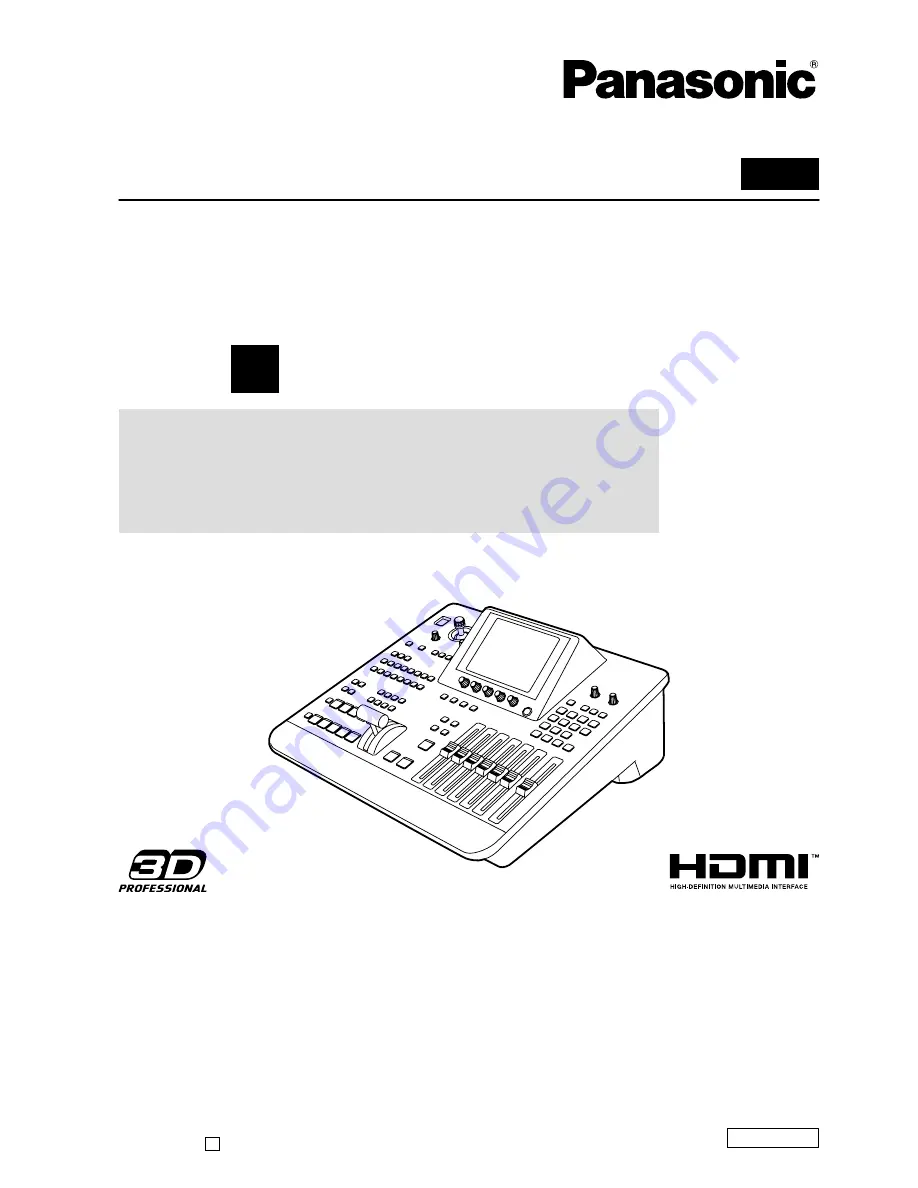
background image

VQT2U23

ENGLISH

SS0810RI0 -PS 

D

Printed in Japan

Operating Instructions 

Vol.1

Digital AV Mixer

Model No.


AG-HMX100P

Model No.


AG-HMX100E

Volume 

1

Note  that  Operating  Instructions  Vol.  1  describes  basic 
operations of the digital AV mixer.
For  instructions  on  advanced  operations  of  the  digital 
AV  mixer,  refer  to  Operating  Instructions  Vol.  2  (pdf  file) 
contained in the supplied CD-ROM.

Before operating this product, please read the instructions carefully and save this manual for future use.

Summary of Contents for AG-HMX100E

Page 1: ... 1 Note that Operating Instructions Vol 1 describes basic operations of the digital AV mixer For instructions on advanced operations of the digital AV mixer refer to Operating Instructions Vol 2 pdf file contained in the supplied CD ROM Before operating this product please read the instructions carefully and save this manual for future use ...

Page 2: ...equipment CAUTION The mains plug of the power supply cord shall remain readily operable The AC receptacle mains socket outlet shall be installed near the equipment and shall be easily accessible To completely disconnect this equipment from the AC mains disconnect the mains plug from the AC receptacle CAUTION In order to maintain adequate ventilation do not install or place this unit in a bookcase ...

Page 3: ...an electrician for replacement of the obsolete outlet 10 Protect the power cord from being walked on or pinched particularly at plugs convenience receptacles and the point where they exit from the apparatus 11 Only use attachments accessories specified by the manufacturer 12 Use only with the cart stand tripod bracket or table specified by the manufacturer or sold with the apparatus When a cart is...

Page 4: ...cordance with the instructions may cause harmful interference to radio communications However there is no guarantee that interference will not occur in a particular installation If this equipment does cause harmful interference to radio or television reception which can be determined by turning the equipment off and on the user is encouraged to try to correct the interference by one of the followi...

Page 5: ...ers on top of the equipment CAUTION Do not remove panel covers by unscrewing them To reduce the risk of electric shock do not remove the covers No user serviceable parts inside Refer servicing to qualified service personnel CAUTION The mains plug of the power supply cord shall remain readily operable The AC receptacle mains socket outlet shall be installed near the equipment and shall be easily ac...

Page 6: ...is plug Should the fuse need to be replaced please ensure that the replacement fuse has a rating of 13 amps and that it is approved by ASTA or BSI to BS1362 Check for the ASTA mark or the BSI mark on the body of the fuse If the plug contains a removable fuse cover you must ensure that it is refitted when the fuse is replaced If you lose the fuse cover the plug must not be used until a replacement ...

Page 7: ...nals Other connecting cables IEEE1394 USB Use shielded cables which provide quality performance for high frequency applications as connecting cables When connecting to the DVI signal terminal use a cable with a ferrite core If your apparatus is supplied with ferrite core s they must be attached on cable s following instructions in this manual 3 Performance level The performance level of the appara...

Page 8: ...Setting Video and Audio Input Sources AUDIO VIDEO 24 Setting the Video Format VIDEO FORMAT 26 Setting the Bus BUS 27 Setting Audio Channels AUDIO CH 27 Setting the Audio Faders AUDIO FADER 27 INT VIDEO Menu Internal Video Setting Screen 28 Setting the Back Matte BACK MATTE 29 Outputting Color Bars COLOR BAR 30 Using Still Pictures or Movies as Internal Video MEMORY 30 Using Video Input from PC PC1...

Page 9: ...affect the recorded images and or sound The liquid crystal parts are highly precise with 99 99 of the pixels effective This leaves less than 0 01 of pixels that may not light or may remain on all the time These phenomena are normal The response speed brightness and color contrast of the liquid crystal parts vary with the operating temperature and viewing angle Operate the CONTRAST control to get t...

Page 10: ...nectors for program output 1 and preview output 2 this unit is equipped with multi view connectors used to display all input sources on the same screen and AUX connectors used for various outputs Waveform display Multi view output displays waveforms for input signal check on the monitor 3D camera supported Two pairs of L and R channels are available to input 3D camera video sources and can be swit...

Page 11: ... external synchronization page Vol 2 28 Setting details for connecting PC page Vol 2 28 Setting for external interface page Vol 2 28 Selecting video to use page 33 Using 3D video page Vol 2 22 Adjusting video page Vol 2 13 Adjusting mixing sound page Vol 2 17 Setting the video switching transition effect page 34 Inserting keying characters or graphics into video page 35 Setting the downstream key ...

Page 12: ...essories Power cable 1 for AG HMX100P 2 for AG HMX100E CD ROM 1 NOTE Be sure to appropriately dispose of the packing material when you have unpacked the product Consult your supplier regarding purchase of accessories ...

Page 13: ...1 13 3 2 5 10 14 6 7 8 21 25 24 27 26 20 18 1 POWER button page 19 2 PROJECTOR REMOTE button pages 18 Vol 2 28 3 ASPECT control and button page 36 4 Joystick pages 20 28 30 34 36 Vol 2 4 Vol 2 6 Vol 2 13 5 Rotary Z control pages 20 28 30 36 Vol 2 13 6 HOLD button pages 34 36 CENTER button pages 34 36 Vol 2 13 SCENE GRABBER button page 36 7 Menu buttons SETUP button page 22 INT VIDEO button page 28...

Page 14: ...utton SOURCE 1 5 2 6 3 7 4 8 buttons INT button 25 EFFECTS buttons for A PROG and B PRESET buses pages Vol 2 13 Vol 2 15 STILL buttons page Vol 2 15 STROBE buttons page Vol 2 15 VIDEO EFFECTS buttons page Vol 2 13 COLOR EFFECTS buttons page Vol 2 13 26 PREVIEW buttons page 33 ME PVW button A PROG selector button B PRESET selector button DSK selector button 27 PATTERN area pages 23 34 36 Vol 2 6 Vo...

Page 15: ... connectors For devices and signals which can be connected to each connector see System Configuration Examples page 16 and Example Connections with 3D Camera pages Vol 2 22 to 24 NOTE For the DVI I IN connector and DVI D IN connectors shielded DVI cables with noise suppression core are recommended For transmitting HD SDI signals via the SDI IN 1 to 4 connectors and SDI OUT connectors cables equiva...

Page 16: ...T PVW SDI OUT AUX DVI D OUT PGM DVI D OUT MULTI VIEW DVI I IN AUDIO IN MIC SDI IN 1 SDI IN 2 SDI IN 3 SDI IN 4 VIDEO IN 1 VIDEO IN 2 SDI OUT MULTI VIEW G L ADV REF Program output Preview output Professional use monitor AUX output Program output Professional use projector Home use television SDI output G L external sync signal 1 Advanced reference signal 1 DVI D output Professional use video camera...

Page 17: ...sional use projector Home use television Professional use video camera Home use video camera Termi nation P2 mobile Professional use camera Professional use camera System camera MIC Professional use audio equipment PC SDI output G L external sync signal 1 Advanced reference signal 1 DVI D output Loop through SDI video and audio input SDI video and audio input HDMI input HDMI input MIC input Analog...

Page 18: ... Signal generator External controller Program output Preview output Professional use LCD monitor Professional use projector Home use television Program output AUX output SDI output DVI D output MIC Professional use audio equipment PC Professional use video camera Home use video camera Termi nation P2 mobile Professional use camera Professional use camera System camera Loop through SDI video and au...

Page 19: ... described below with the SETUP menu page 22 and INT VIDEO menu page 28 to set up this unit Setting the startup mode page 22 Changing direct patterns page 23 Setting video and audio input sources page 24 Setting the video format page 26 Setting the bus page 27 Setting the audio output channels page 27 Setting the audio fader page 27 Setting the back matte video page 29 Outputting the color bars pa...

Page 20: ...HDMI1 FORMAT Input source of the HDMI IN 1 connector is in unavailable format CHANGE HDMI2 FORMAT Input source of the HDMI IN 2 connector is in unavailable format Change the system format setting or the input source setting NOTE The FAN STOP error message is also displayed on the multi view screen However since the multi view screen does not open when this unit is in 3D mode page Vol 2 25 no error...

Page 21: ...ON Setting transition wipe page Vol 2 3 KEY LEARN Setting key learn page Vol 2 9 TITLE KEY Setting the title key page Vol 2 8 PROJECTOR Setting the projector page Vol 2 29 To select the menu For the SETUP INT VIDEO DSK FADE and AUDIO EFFECTS menus press the corresponding menu button For other menus press the operation button related to the settings For more information see the description of each ...

Page 22: ...otary 3 Rotary 4 Rotary 5 RESET PRESET FACTORY MODE RESET POWER To reset settings other than basic settings to the factory default settings when the unit is restarted Set POWER to RESET reset mode using the rotary 2 control Settings other than SETUP menu settings direct pattern settings event memory settings file settings and key learn settings are reset to the factory default settings To reset al...

Page 23: ...ton of the pattern you want to change The selected button flashes 4 Enter the number of the pattern you want to set for transition or as the key using the numeric keys in the numeric key area You can select the number from 0XXX 1XXX and 2XXX for transition patterns 3XXX for key patterns and 9000 to 9019 for key learn The setting screen switches to the DIRECT PATTERN TRANSITION screen or DIRECT PAT...

Page 24: ... for the following three cases When the system format setting is SD page 19 When the system format setting is HD page 19 3D mode setting is other than OFF The stored settings are read out each time the system format is changed To display the Audio Video Input Source Setting screen 1 Set INPUT to SETUP using the rotary 2 control and press the key 2 When the message OK appears press the key again Th...

Page 25: ...put and analog input as the audio input sources A S 1 to A S 4 using the rotary 5 control NOTE If the system format is set to SD page 19 HDMI cannot be selected If the system format is set to HD VIDEO cannot be selected You cannot set the combinations of video and audio input sources shown in the table below The settings are automatically changed to available values When the video input is HDMI on...

Page 26: ...e INT VIDEO menu page 28 and the title memory setting page 30 Rotary 1 Rotary 2 Rotary 3 Rotary 4 Rotary 5 0 7 5 4 3 16 9 480 59i 576 50i 720 50p 720 59p 1080 50i 1080 59i HDMI VIDEO 1080 59i 7 5 SET UP FORMAT 16 9 ASPECT AG HMX100P Rotary 1 Rotary 2 Rotary 3 Rotary 4 Rotary 5 0 7 5 4 3 16 9 480 59i 576 50i 720 50p 720 59p 1080 50i 1080 59i HDMI VIDEO 1080 59i 0 SETUP FORMAT 16 9 ASPECT AG HMX100E...

Page 27: ... assigned Rotary 1 Rotary 2 Rotary 3 Rotary 4 Rotary 5 1 8 1 4 1 8 1 4 OFF ON SDI1 SDI2 SDI3 SDI4 CH CH AUDIO SDI1 1 2 ON L CH R CH OSD 1 Set CH to one of SDI1 SDI2 SDI3 or SDI4 SDI inputs 1 to 4 using the rotary 2 control 2 Use the rotary 3 control to select the audio input of the SDI input selected in Step 1 which you want to assign the L channel by setting L CH to the desired audio input number...

Page 28: ...e SETUP menu To set the audio output format and the operation of audio faders Set SOURCE to CP PAIR BUS SEP1 BUS SEP2 12 PAIR or 12 SEPA using the rotary 2 control The following table shows the output method and audio input sources assigned to the faders for each setting Setting Output Method SOURCE 1 5 Fader SOURCE 2 6 Fader SOURCE 3 7 Fader SOURCE 4 8 Fader CP PAIR Sound output of the selected i...

Page 29: ...ack matte using the rotary 3 control and set PATTERN to OFF using the rotary 4 control 4 If CUSTOM1 or CUSTOM2 is selected in Step 2 use the joystick and rotary Z control to set the PB and PR values in the range of 0 to 255 and the Y value in the range of 16 to 235 for selecting the back matte video color If other than CUSTOM1 and CUSTOM2 is selected set the color level the Y signal level for whit...

Page 30: ...ture or movie The page count ratio for the title and still picture or movie can be changed from the MEMORY submenu of the SETUP menu page Vol 2 27 Use the MEMORY submenu of the INT VIDEO menu to create and display still pictures and movies If a still picture is created ST STILL and the number of pages are displayed in the internal video display area in the upper portion of the Setting screen If a ...

Page 31: ...saved still picture NOTE When the system format is set to 720 no change is given to video due to progressive video even if switching is made between FIELD and FRAME To save movies used as internal video Rotary 1 Rotary 2 Rotary 3 Rotary 4 Rotary 5 1 30 480i 1 30 576i 1 14 720p 1 6 1080i 1 30 480i 1 30 576i 1 14 720p 1 6 1080i REPEAT ONCE WRITE PREVIEW EXIT PAGE MEMORY 1 WRITE FRAME 2 MODE REPEAT 1...

Page 32: ...is unit via the DVI I IN connector For using video created on PC it is necessary to allocate the DVI I input to an input source number in the AUDIO VIDEO submenu of the SETUP menu in advance page 24 The source input from PC is set from the PC1 submenu of the SETUP menu Rotary 1 Rotary 2 Rotary 3 Rotary 4 Rotary 5 ANALOG DIGITAL XGA WXGA SXGA 1080 50p 1080 60p _ _ ON OFF PC1 ANALOG A SET FORMAT SXG...

Page 33: ...eck sound The output from the SDI PVW OUT connector can be changed with the following PREVIEW buttons ME PVW button Used to check switching and combined effects Allows you to check the switched image and the image currently being switched page 34 or the image to be combined and the image currently being combined page 35 A PROG selector button Allows you to check the input program input source of b...

Page 34: ...lected pattern by applying effects including border shadow and trail page Vol 2 3 6 Set the pattern position transition start position using the joystick Press the CENTER button to turn on and the pattern position is set to the center Press the HOLD button to turn on and the joystick is fixed to the current position NOTE There are some patterns for which the position cannot be adjusted with the jo...

Page 35: ...rames page Vol 2 26 3 Press the key Program Preset Transition Program preset transition is an effect of switching from program video base video to preset video video used as an effect and vice versa It is executed in the same method as described in AB Transition except for setting TYPE to PRG PRE in Step 1 The ONE WAY button is disabled because it limits the switching direction only from preset vi...

Page 36: ...e transition time from combining start to end page 35 8 Slide the transition lever to the B side or A side or press the AUTO TAKE button When the AUTO TAKE button is pressed it is lighted and source video A is combined with B or source video B is combined with A To use the Scene Grabber function Press the SCENE GRABBER button to turn on The scene grabber function allows you to move the image curre...

Page 37: ...button is lighted and flashes while the key is being inserted To use a transition pattern as DSK Press the DSK EFFECTS button to turn on and select a transition pattern instead of selecting preset video page 35 The dissolve effect is applied NOTE It is impossible to use a pattern other than transition patterns for DSK If a pattern unavailable for DSK is selected the DSK EFFECTS button flashes To s...

Page 38: ...n again The button goes off and fade in is executed To synchronize the audio faders to the transition lever Press the AUDIO FOLLOW VIDEO button to turn on To set the FADE transition time The currently set FADE transition time FADE TIME is shown in the area where the event number transition time pattern number and internal video are displayed on the setting screen page 20 The factory default settin...

Page 39: ...switched on Are the cables connected correctly Has fade has been applied Has the source been input correctly There is no color Is the video effect or color effect set to ON Is only component Y signal provided as input instead of the composite signal Has the source been input correctly There is no sound Has audio fade out been applied Has the source been input correctly The image does not change ev...

Page 40: ...SD format Y 13 5 MHz PB PR 6 75 MHz HD format Y 74 176 MHz PB PR 37 088 MHz 1080 59 94i 720 59 94p 1080 23 98PsF Y 74 25 MHz PB PR 37 125 MHz 1080 50i 720 50p Video format SD 480 59 94i 576 50i HD 720 59 94p 720 50p 1080 59 94i 1080 50i 1080 23 98PsF for 3D video only Quantization 10 bits Internal processing 4 2 2 4 12 bits AUDIO Sampling frequency 48 kHz digital input synchronizes with video sign...

Page 41: ...TE292M 296M 299M standards DVI D x 1 TMDS single link incompatible with HDCP 3D mode R channel signal for MODE1 SIDE BY SIDE signal for MODE2 Advanced reference output ADV REF BNC x 1 75 Ω Analog composite signal Sync 0 286 V p p NTSC 0 3 V p p PAL Burst 0 286 V p p NTSC 0 3 V p p PAL AUDIO INPUT OUTPUT Audio input AUDIO IN XLR 4 sets pair of L and R 4 0 3 dBu switchable balanced 10 kΩ SDI Embedde...

Page 42: ...576 50i Yes Yes 576 50p 720 50p Yes Yes Yes 720 59 94p Yes Yes Yes 1035 59 94i 1 Yes 1080 25p over 50i Yes 1080 29 97p over 59 94i Yes 1080 50i Yes Yes Yes 1080 59 94i Yes Yes Yes 1 Treated as 1080 59 94i Format VIDEO SDI HDMI DVI D DVI I 640 480 60Hz Yes 1 1024 768 60Hz Yes 1280 768 60Hz Yes 1280 1024 60Hz Yes 1920 1080 50Hz Yes 1920 1080 60Hz Yes 1 If HDMI is selected the HDMI input signal is ou...

Page 43: ...4p Yes 1035 59 94i 1 1080 23 98PsF Yes 1080 23 98p over 59 94i Yes 1080 25PsF Yes 1080 25p over 50i Yes 1080 29 97PsF Yes 1080 29 97p over 59 94i Yes 1080 50i Yes 1080 59 94i Yes 1 Treated as 1080 59 94i Inrush current measured according to European standard EN55103 1 15 A Mass and dimensions are approximate values Specifications are subject to change without notice ...

Page 44: ...ts 5 Key Learn 5 Pattern edge 5 BASIC PATTERN KEY menu 5 BORDER 7 8 9 B PRESET bus source selector buttons 14 24 INT button 14 SHIFT button 14 SOURCE 1 5 2 6 3 7 4 8 buttons 14 B PRESET selector button 14 33 BUS 27 Bus setting 27 C CENTER button 13 34 36 13 Chroma key 6 Border 7 Color canceling 6 Cropping 7 Effects 7 Key setting 6 CHROMA KEY button 14 6 CHROMA KEY menu 6 COLOR BAR 30 Color bar out...

Page 45: ...9 G GEN LOCK 28 G L connector 15 16 18 24 28 GND terminal 15 GPI connector 15 26 GPI control of video effects 26 Gradation 29 H HDMI IN 1 2 connectors 15 17 18 HD video processing system configuration 17 HOLD button 13 34 36 Hours meter 26 I Initial setup 19 Input sources 33 Setting 24 Internal video 33 Setting screen 28 INT VIDEO button 13 28 INT VIDEO menu 28 J Joystick 13 20 28 30 34 36 4 6 13 ...

Page 46: ...reen 20 Setup 22 Operation screen 22 SETUP button 13 22 SETUP menu 22 26 Shadow SHADOW 4 SHIFT key 14 27 28 30 32 33 4 9 10 13 15 SOURCE 1 5 2 6 3 7 4 8 faders 14 27 Startup mode 22 Still 15 STILL buttons 15 Still pictures displaying 31 Still pictures saving as internal video 31 Strobe 15 STROBE buttons 15 SYSTEM1 26 SYSTEM2 26 System configuration examples 16 System settings 26 T TALLY connector ...

Page 47: ...MEMO 47 ...

Page 48: ...s waste in accordance with national legislation For business users in the European Union If you wish to discard electrical and electronic equipment please contact your dealer or supplier for further information Information on Disposal in other Countries outside the European Union This symbol is only valid in the European Union If you wish to discard this product please contact your local authoriti...

Page 49: ...e that Operating Instructions Vol 2 describes advanced operations of the digital AV mixer For instructions on basic operations of the digital AV mixer refer to Operating Instructions Vol 1 printed document supplied with this unit Before operating this product please read the instructions carefully and save this manual for future use ...

Page 50: ...e Event Memory 21 Chapter 3 Switching 3D Video Example Connections with 3D Camera 22 System for Monitoring Program Output as L channel and Multi view Output as R Channel Simultaneous Display of L and R Channels 22 System for Displaying Program Output and Multi view Output on Different Monitors Use of SIDE BY SIDE Signal 23 System Configured with 2 Units of AG HMX100P HMX100E and 4 Cameras 24 Setti...

Page 51: ... the patterns shown as Basic in List of Transition Patterns at the back of this document and their related patterns Rotary 1 Rotary 2 Rotary 3 Rotary 4 Rotary 5 OFF COMP SLIDE MULTI BLINDS MODIFY OFF Select the effect to be applied to the pattern using the rotary 2 control When COMP is selected the effect level SINGLE or DOUBLE can be set with the rotary 3 control Modify Description Level Example ...

Page 52: ... shadow to the pattern TRAIL Leaves trails of the moving pattern Select OFF to apply no effect Rotary 1 Rotary 2 Rotary 3 Rotary 4 Rotary 5 OFF SHADOW TRAIL EFFECTS OFF If SHADOW is selected Rotary 1 Rotary 2 Rotary 3 Rotary 4 Rotary 5 EFFECTS SHADOW Set the position of the shadow by operating the joystick while holding down the SHIFT key The CENTER SCENE GRABBER and HOLD buttons flash temporarily...

Page 53: ...ler the setting value the higher the transparency When 0 is set the key disappears entirely becomes transparent The key registered in the direct patterns can be individually set for each pattern CROP for PATTERN KEY menu only Video used as the key can be cropped Rotary 1 Rotary 2 Rotary 3 Rotary 4 Rotary 5 0 243 480i 0 288 576i 0 720 720p 0 540 1080i 0 243 480i 0 288 576i 0 720 720p 0 540 1080i 0 ...

Page 54: ...y in the menu appears when the color is not stored The color can be stored any number of times by pressing the key However the color data is overwritten each time it is stored To cancel the stored color enter the selected number using the numeric keys while holding down the SHIFT key To set the chroma key in detail The color density and range can be specified to designate more precise keying Set S...

Page 55: ...ANCE KEY External Key EXT KEY Luminance keying is a function for creating a key with the specific brightness luminance of one image as the reference and keying to another image External keying is a function for keying a specified extraneous image The external keying function enables keying of an image which is not assigned as the input source The following diagram shows an example of the luminance...

Page 56: ...ngs can be made in the same way as in the EFFECTS submenu of the TRANSITION menu page 4 BORDER Settings can be made in the same way as in the BORDER submenu of the CHROMA KEY menu page 7 Setting the Title Key TITLE KEY A still picture saved in memory from the DSK menu can be keyed as a title Title keys are saved as patterns of the numbers with 1 as the last digit every 10th 9511 9521 in the range ...

Page 57: ...or the selected pattern the message OK appears In this case press the key again to display the Key Learn Editing screen NOTE When key learn that is already registered in a pattern is edited the settings of the original pattern before key learn was set are given priority Thus even if the pattern with key learn set is called and SETUP is selected no change is given to the base pattern For key learn ...

Page 58: ...message OK appears press the key again To cancel the pattern deletion press the key while holding down the SHIFT key When CLR is selected the currently selected key learn pattern is deleted When ALL CLR is selected all key learn patterns are deleted To use a pattern with key learn set Key learn is set in the patterns in the range of No 9000 to No 9019 When one of those patterns is selected BASIC P...

Page 59: ... DVI I and TITLE still picture saved in title memory To select the key fill video Use the rotary 3 control BODMAT border matte can also be selected as well as SDI1 to SDI4 HDMI1 HDMI2 VIDEO1 VIDEO2 DVI I and TITLE still picture saved in title memory To save DSK as a title key 1 Use the rotary 4 control to select the page number of memory where the title is saved 2 Set MODE to WRITE using the rotar...

Page 60: ...utton The factory default setting is OFF Operate the rotary 3 control to set the direction of the slide in operation when DSK is ON The factory default setting is OFF Operate the rotary 4 control to set the direction of the slide out operation when DSK is ON w Sliding toward the left q Sliding toward the right e Sliding toward the top r Sliding toward the bottom The factory default setting is OFF ...

Page 61: ... At that time the joystick rotary Z control settings and 3D display area of the setting screen page Vol 1 20 shows the PB PR and C GAIN values To set the color saturation to 0 temporarily Press the CENTER button during operation of the COLOR EFFECTS menu the color saturation can be set to zero temporarily NOTE If the No 221 or 222 1068 or 1069 pattern is selected the MIX pattern with the color eff...

Page 62: ...and 202 patterns DEFOCUS The video effect of purposely displacing the focus can be set to perform fantastical rendering or get the attention of viewers The following diagram shows an example of the defocus effect Defocus effect Rotary 1 Rotary 2 Rotary 3 Rotary 4 Rotary 5 OFF ON 0 7 DEFOCUS OFF LEVEL 0 Select ON or OFF to specify whether or not to apply the effect using the rotary 2 control The fa...

Page 63: ...The factory default setting is 1 A numeric value such as 4 is set to specify the number of screens into which the screen is divided for strobe image display When is given to a numeric value The strobe image is sequentially displayed only once on each of the screens divided according to the value When R is given It is repeated to sequentially display the strobe image on each of the screens divided ...

Page 64: ... 2 control The factory default setting is OFF Set LEVEL in the range of 0 to 7 using the rotary 3 control The factory default setting is 4 This level setting is applied to No 1034 211 transition pattern NEGA The brightness of video can be inverted The following diagram shows an example of the negative effect Negative effect Rotary 1 Rotary 2 Rotary 3 Rotary 4 Rotary 5 OFF ON OFF ON NEGA OFF C Y OF...

Page 65: ...he channel to be emphasized L Left channel R Right channel L R Both left and right channels The factory default setting is L Set BALANCE in the range of L7 to 0 and 0 to R7 using the rotary 5 control BALANCE is used to select whether to expose the channel selected with IN CH toward the right direction R or left direction L and to set the gap from the center position using a numeric value The facto...

Page 66: ...fault setting is OFF Select UP or DOWN for PITCH to specify whether to increase or decrease the sound pitch using the rotary 4 control The factory default setting is UP Set LEVEL in the range of 0 to 10 using the rotary 5 control The factory default setting is 5 MUTE Rotary 1 Rotary 2 Rotary 3 Rotary 4 Rotary 5 OFF AB OFF 12dB 20dB 60dB AB ABAUX ALL MUTE Select the mute level from 12dB 20dB and 60...

Page 67: ...AVE RECALL ALL CLR EMPTY FILE 1 SAVE To select a file to operate Select the file number from 1 to 8 using the rotary 2 control When the file of the selected number is null EMPTY is shown When the file is already saved SAVED is shown To save the current settings in a file Select SAVE using the rotary 3 control When the message OK appears press the key To cancel the file save press the key while hol...

Page 68: ...r decrement the value using the or key respectively 3 To call the settings press the key The EVENT RECALL button goes off The selected event is called and the settings of the setting screen are changed to those registered as the event 4 Press the AUTO TAKE button The effects registered as the event are executed If one of the events in which a series of effects were registered is called If 10 event...

Page 69: ...g Settings and Effects Clearing All the Event Memory 1 Press the EVENT RECALL button The button is lighted 2 Press the period key twice is displayed instead of an event number 3 Press the key while holding down the SHIFT key ...

Page 70: ... the input sources to two units of AG HMX100P HMX100E NOTE The 3D video production systems shown below cannot perform preview output AUX output can be used only for input source check Of the video switching effects only cut can be executed When 3DFORMAT is set to 1080 23PsF in 3D mode this unit cannot be synchronized with an external signal generator Chapter 3 Switching 3D Video System for Monitor...

Page 71: ...signals in the horizontal direction Program output and multi view output are the same signal 3D mode is set to MODE2 page 25 DVI D OUT PGM DVI D OUT MULTI VIEW SDI IN 1 L R SDI IN 2 SDI IN 3 SDI IN 4 ADV REF SDI OUT PGM SDI OUT MULTI VIEW AG HMX100P HMX100E Professional use 3D monitor P2 mobile SDI output SDI video and audio input DVI D output Advanced reference signal 1 Professional use 3D integr...

Page 72: ... audio output from the master unit In order to synchronize two units of AG HMX100P HMX100E be sure to connect a signal generator and input the same synch signal SDI IN 2 DVI D OUT PGM RS 232C RS 232C G L G L SDI IN 1 SDI IN 2 SDI IN 3 SDI IN 4 SDI IN 3 SDI IN 1 SDI IN 4 SDI OUT PGM DVI D OUT PGM SDI OUT PGM L R L R L R L R L R Professional use 3D monitor SDI output SDI video and audio input SDI ou...

Page 73: ...slave Setting Screen in 3D Mode If the 3D mode is set to other than OFF 3D appears in the Joystick Rotary Z Control Settings and 3D Display Area The same content as in 2D mode is displayed in the area upper than the menu display area but not used for the operation POS MOSAIC SIZE OFF XY 0 OFF 0 DEFOCUS LEVEL OFF MONO EVENT VIDEO EFFECTS CH A ME TIME PATTERN INT 00E 2 00F 3044 WHT X 128 Z 196 FAN S...

Page 74: ...n In one of the following cases the time counter is reset and immediately restarted A button has been operated on the operation panel This unit has been externally operated through RS 232C or GPI control Video signal is being input to a connector of this unit To set the time until the screen saver is executed Operate the rotary 3 control to select the time until the screen saver is executed to pro...

Page 75: ...ively 2 Press the key with displayed The message OK appears 3 Press the key again to fix the change To cancel the change press the key while holding down the SHIFT key If other menu screen is displayed when is being displayed the settings return to the previous values without being updated The factory default settings are as shown below Video Format INT V TITLE 1080 59i 3 3 1080 50i 3 3 720 59p 7 ...

Page 76: ...ry 5 0 60 0 300 1 0 20 0 31 1200 1500 2 1500 1800 3 1500 1800 4 HPOSI PC2 30 1000 CLOCK VPOSI 10 PHASE 16 1 When PC1 is 1080 50 or 1080 60 2 When PC1 is XGA 3 When PC1 is WXGA 4 When PC1 is SXGA Set H POSI horizontal position using the rotary 2 control Set V POSI vertical position using the rotary 3 control Set PHASE using the rotary 4 control Set CLOCK using the rotary 5 control Only an even numb...

Page 77: ...ollowing speeds can be selected Setting Baud Rate 9 6 k 9600 bps 19 2 k 19200 bps 38 4 k 38400 bps 115 2 k 115200 bps The factory default setting is 9 6 k To set the data length Set DATA L to 8BITS or 7BITS using the rotary 3 control The factory default setting is 8BITS To set the communication parity Set PARITY to NONE not set ODD odd bit or EVEN even bit using the rotary 4 control To select the ...

Page 78: ...re output from the PGM connector of the SDI and DVI D connectors to projectors without shutter function NOTE If the communication is interrupted during control of the projector operational consistency may not be maintained between this unit and the projector For example if the communication cable is disconnected after the shutter is turned off from the unit the black signal is output from the PGM ...

Page 79: ...ts 5 Key Learn 5 Pattern edge 5 BASIC PATTERN KEY menu 5 BORDER 7 8 9 B PRESET bus source selector buttons 14 24 INT button 14 SHIFT button 14 SOURCE 1 5 2 6 3 7 4 8 buttons 14 B PRESET selector button 14 33 BUS 27 Bus setting 27 C CENTER button 13 34 36 13 Chroma key 6 Border 7 Color canceling 6 Cropping 7 Effects 7 Key setting 6 CHROMA KEY button 14 6 CHROMA KEY menu 6 COLOR BAR 30 Color bar out...

Page 80: ...19 G GEN LOCK 28 G L connector 15 16 18 24 28 GND terminal 15 GPI connector 15 26 GPI control of video effects 26 Gradation 29 H HDMI IN 1 2 connectors 15 17 18 HD video processing system configuration 17 HOLD button 13 34 36 Hours meter 26 I Initial setup 19 Input sources 33 Setting 24 Internal video 33 Setting screen 28 INT VIDEO button 13 28 INT VIDEO menu 28 J Joystick 13 20 28 30 34 36 4 6 13...

Page 81: ...reen 20 Setup 22 Operation screen 22 SETUP button 13 22 SETUP menu 22 26 Shadow SHADOW 4 SHIFT key 14 27 28 30 32 33 4 9 10 13 15 SOURCE 1 5 2 6 3 7 4 8 faders 14 27 Startup mode 22 Still 15 STILL buttons 15 Still pictures displaying 31 Still pictures saving as internal video 31 Strobe 15 STROBE buttons 15 SYSTEM1 26 SYSTEM2 26 System configuration examples 16 System settings 26 T TALLY connector ...

Page 82: ...O R O R O R O R O R O R O R O R O R O R O R O R O R O R O R O R O R O R O R O R O R O R O R O R O R O R O R O R O R O R O R A O R XY A O R XY A O R XY A O R XY A O R XY A O R XY O R O R O R O R O R O R O R O R O R O R O R O R O R O R O R O R 28 1501 1521 29 1502 1522 30 1503 1523 31 1504 1524 36 1505 1525 37 1506 1526 38 1507 1527 39 1508 1528 40 1509 1529 41 1510 1530 42 1511 1531 128 1512 1532 1...

Page 83: ...cus H Mirror V Mirror 206 1023 207 1030 208 1031 HV Mirror Nega YC Nega Y 209 1032 210 1033 211 1034 Nega C Mono Paint Shutter 1 4 STILL STILL STILL STILL 223 1091 224 1092 225 1093 226 1094 O R O R O R O R Direct Pattern 241 242 243 DT 1 DT 2 DT 3 244 245 246 DT 4 DT 5 DT 6 247 DT 7 Panel 99 0 Panel Panel O R O R Duplicated Duplicated Duplicated Duplicated Duplicated Duplicated 1 Any DVE or Shutt...

Page 84: ...9000 9001 9002 Key Learn1 Key Learn2 Key Learn3 9003 9004 9005 Key Learn4 Key Learn5 Key Learn6 9006 9007 9008 Key Learn7 Key Learn8 Key Learn9 9009 Key Learn10 9010 9011 9012 Key Learn11 Key Learn12 Key Learn13 9013 9014 9015 Key Learn14 Key Learn15 Key Learn16 9016 9017 9018 Key Learn17 Key Learn18 Key Learn19 9019 Key Learn20 Title Diss 9501 9511 9521 T 1 T 2 T 3 9531 9541 9551 T 4 T 5 T 6 9561...

Page 85: ...s waste in accordance with national legislation For business users in the European Union If you wish to discard electrical and electronic equipment please contact your dealer or supplier for further information Information on Disposal in other Countries outside the European Union This symbol is only valid in the European Union If you wish to discard this product please contact your local authoriti...

Page 86: ...AG HMX100 Digital AV Mixer HD SD and 3D Compatible Digital AV Mixer ...

Page 87: ...Live Relays with a Com Versatile HD ...

Page 88: ... V V V V VI V I I I I I I I I i i i inp np np p nput u ut t a acc c cc c ccommodate ays Preview PVW Program PGM M M M M M M M M M M M M M M M Mu ul ul u u ul ul ul u u ti ti ti ti t t V V V V V V V ie ie ie e e i w w w w w fu func n nc n n tion displa a single monitor a an an an an an n an n an and d d d d d d d al al al al al al all l l l so so so o ou ur ur u ce ce c i i im mages on a M is built...

Page 89: ...I input capable of inputting motion or still images from a PC This provides up to 7 channels of video input 6 video outputs 4 SDI outputs Program PGM Preview PVW Multipurpose AUX and Multi View and 2 DVI D outputs Program PGM and Multi View Transitions and Digital Effects Transitions Over 100 wipe patterns and mixes combine with effects like chroma keying luminance keying DSK and fading M E previe...

Page 90: ...ctor Control Function The power switch and shutter for Panasonic professional projectors can be turned on and off by RS 232C remote control This allows convenient projector use during live events Functions for More Comfortable Operation Pattern preset Up to 7 transition patterns and 6 key patterns can be directly registered for retrieval with a single touch Event memory Records the setting conditi...

Page 91: ...F EXT REF Supported signals 1080 59 94i 1080 50i 720 59 94p 720 50p 1080 23 98psf A Professional HD 3D Production System The AG HMX100 Digital AV Mixer fully supports the Panasonic shift toward 3D world Combined with the Panasonic AG 3DA1 Integrated Twin Lens 3D Camera Recorder and the 3D compatible BT 3DL2550 Professional LCD Video Monitor which lets you view 3D footage on site this professional ...

Page 92: ...es Memory Card Portable Recorder AJ HPM200 AJ HPM200 Synchronization signal RS 422A Controller RS 422A Synchronization signal Synchronization signal Synchronization signal Synchronization signal Synchronization signal P2 Card Lch video signal P2 Card Rch video signal HD SDI L HD SDI L HD SDI L HD SDI L HD SDI R HD SDI R HD SDI R HD SDI R HD SDI L HD SDI R HD SDI L HD SDI R HD SDI L HD SDI R AG 3DA...

Page 93: ...R BT 656 4 standards HD serial digital signal SMPTE292M 296M 299M standards HDMI Embedded Audio connector x 2 sets Type A connector incompatible with HDCP and VIERA Link AUX input Pin jack x 1 L and R 10 dBv High impedance unbalanced Microphone input MIC M6 x 1 60 dBV 2 k monaural unbalanced Audio output AUDIO OUT Program PGM output XLR x 1 L and R 4 0 3 dBu switchable Low impedance balanced SDI B...

Reviews: