


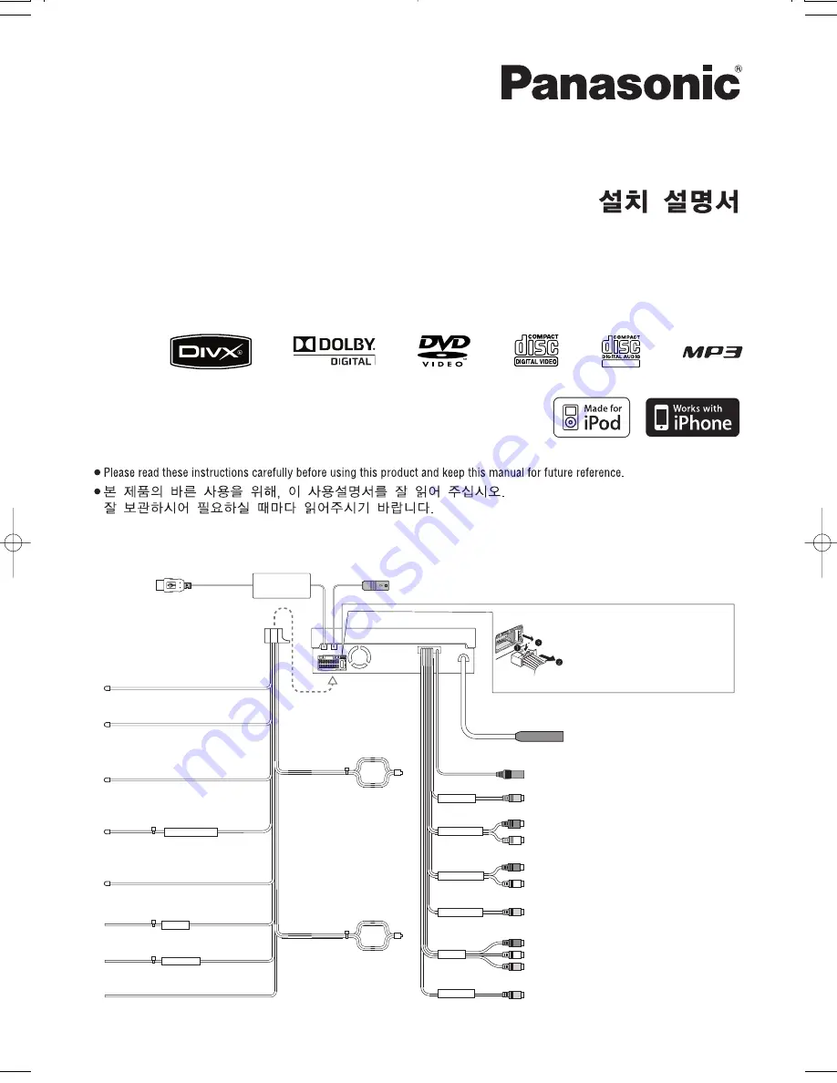
Installation Instructions
PRE OUT REAR
PRE OUT FRONT
AV2 IN
CAMERA IN
VIDEO OUT
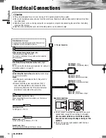
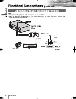
Electrical Connections /
전기 접속
Power Connector/
전원 커넥터
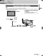
Video Output Terminal (VIDEO OUT)/
비디오 출력 단자 (VIDEO OUT)
Radio Antenna Connector (RADIO ANT IN)/
무선 안테나 커넥터 (RADIO ANT IN)
CQ-VX220W
Pre-Out Connector (front)/
프리아웃 커넥터 (프런트)
Pre-Out Connector (rear)/
프리아웃 커넥터 (리어)
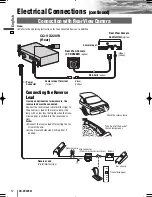
Camera Input Terminal (CAMERA IN)/
카메라 입력 단자 (CAMERA IN)
SIDE BRAKE
ACC
BATTERY 15 A
Reverse Lead/
리버스 리드선
(Violet/white stripe)
(자색/백색 줄무늬)
Navi Mute Lead/
내비 뮤트 리드선
(Orange)
(오렌지색)
Motor Antenna Relay Control Lead/
모터 안테나 중계 컨트롤 리드선
(Blue)
(청색)
Side Brake (Parking Brake) Connection Lead/
사이드 브레이크 (주차 브레이크) 접속 리드선
(Bright green)
(밝은 녹색)
External Amplifier Control Power Lead
외부 앰프 컨트롤 전원 리드선
(Blue/white stripe)
(청색/백색 줄무늬)
Power Lead/
전원 리드선
(Red)
(적색)
(Yellow)
(황색)
Battery Lead/
배터리 리드선
Ground Lead/
접지 리드선
(Black)
(검정)
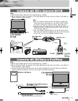
Audio/Video Input Terminal (AV2 IN)/
오디오/비디오 입력 단자 (AV2 IN)
(R)
(우)
(Red)
(적색)
(L)
(좌)
(White)
(백색)
(R)
(우)
(Red)
(적색)
(L)
(좌)
(White)
(백색)
(Yellow)
(황색)
(R)
(우)
(Red)
(적색)
(L)
(좌)
(White)
(백색)
(Yellow)
(황색)
(Yellow)
(황색)
*Fuse (15 A)
Refer fuse replacement to your nearest
authorized Panasonic Service Center. Do not try fuse
replacement by yourself.
*
퓨즈(15 A)
퓨즈 교환은 가까운 파나소닉 서비스
센터에 의뢰해 주십시오. 절대로 고객 자신이 퓨즈를
교환하지 마십시오.
System-up Connector/
시스템 업 커넥터
USB Connector/
USB 커넥터
RGB Connector/
RGB 커넥터
Front Right +
(Gray)
Front Right –
(Gray/black stripe)
우측 전면
+
(회색)
우측 전면
–
(회색/검정 줄무늬)
Front Left +
(White)
Front Left –
(White/black stripe)
좌측 전면
+
(백색)
좌측 전면
–
(백색/검정 줄무늬)
Rear Right +
(Violet)
Rear Right –
(Violet/black stripe)
우측 후부
+
(자색)
우측 후부
–
(자색/검정 줄무늬)
Rear Left +
(Green)
Rear Left –
(Green/black stripe)
좌측 후부
+
(녹색)
좌측 후부
–
(녹색/검정 줄무늬)
EXT VIDEO IN
Video Input Terminal (EXT VIDEO IN)/
비디오 입력 단자 (EXT VIDEO IN)
(Yellow)
(황색)
Model:
CQ-VX220W
TEXT
VX220W̲II̲001̲cov.qxd 09.2.24 7:20 PM ページ2
Summary of Contents for CQ-VX220W
Page 18: ...34 CQ VX220W Memorandum...
Page 19: ...35 CQ VX220W...


