background image

 1 

SCHEMATIC DIAGRAM 

2

 2 

WIRING CONNECTION DIAGRAM 

2

 3 

DISASSEMBLY / ASSEMBLY INSTRUCTIONS 

3

©

2000 Matsushita Electric Works Ltd. All rights

reserved. Unauthorized copying and distribution is a
violation of law.

EY3654

 4 

TROUBLE SHOOTING GUIDE 

6

 5 

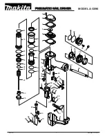
EXPLODED VIEW 

7

 6 

REPLACEMENT PARTS LIST 

8

Variable Speed Cordless Sealing Gun

SPECIFICATIONS

Motor voltage

: DC Motor 7.2V

Ejection pressure

: 2,500N ( 250kgf )

Length overall

: max. 892mm ( 35" ), min. 550mm ( 22" )

Weight (with battery pack)

: 2.1kg ( 4.6 lbs )

CONTENTS

 Page 

Page

ORDER NO. PTD0009U36C1

Summary of Contents for EY3654 - 7.2V CAULKING GUN

Page 1: ... copying and distribution is a violation of law EY3654 4 TROUBLE SHOOTING GUIDE 6 5 EXPLODED VIEW 7 6 REPLACEMENT PARTS LIST 8 Variable Speed Cordless Sealing Gun SPECIFICATIONS Motor voltage DC Motor 7 2V Ejection pressure 2 500N 250kgf Length overall max 892mm 35 min 550mm 22 Weight with battery pack 2 1kg 4 6 lbs CONTENTS Page Page ORDER NO PTD0009U36C1 ...

Page 2: ...1 SCHEMATIC DIAGRAM 2 WIRING CONNECTION DIAGRAM 2 EY3654 ...

Page 3: ... NOTE To open housing A and B unhook one part of housing using a flatted screw driver NOTE When assembling housing A and B fit housing hooks each other first Ref No 1B Procedure 1A 1B Removal of driving block 1 Remove one housing screw and one release lever screw 2 Take driving block out 3 Remove one screw on radiating board 3 EY3654 ...

Page 4: ...w speed Ref No 1D Procedure 1A 1B 1C 1D Removal of driving block 1 Remove counter gear transfer gear and internal gear NOTE Check proper direction of internal gears when assembling 2 Remove driving shaft NOTE Do not lose stick 3 Remove clutch key and coil spring NOTE Check proper positioning and direction of clutch key and coil spring when assembling 4 Remove two screws of pinion cover 5 Remove pi...

Page 5: ...are all same For connection A confirm position or deformationof switch lever For connection B take switch lever off Ref No 1F Procedure 1A 1B 1C 1D 1E 1F Removal of rack 1 Take out spring pin using ø3mm stick NOTE When taking pinion gear out rack may move freely 2 Pull out rack forward CHECK POINT When rack does not move pushing release lever there is a possibility to cause that the part of pinion...

Page 6: ...SWITCH Replace micro switch See WIRING CONNECTION DIAGRAM 1 When lever is slightly depressed There should be continuity between 1 and 3 There is no continuity between 1 and 2 or 2 and 3 2 When lever is not depressed There should be continuity between 1 and 2 There is no continuity between 1 and 3 or 2 and 3 NO Does not CHECK VAROAB ERESOSTAMCE Replace variable speedcontrol Disconnect white leae wi...

Page 7: ...5 EXPLODED VIEW EY3654 7 ...

Page 8: ...D CONTROL 1 28 WEY3653L2548 VARIABLE RESISTANCE 1 29 WEY3653L2128 MODULE 1 30 WEY3653L2108 FET 1 31 WEY3653L2948 LEAD WIRE SET B 6 32 WEY3652L2008 MICRO SWITCH A 1 33 WEY3652L2018 MICRO SWITCH B 1 34 WEY3650B0577 SWITCH FRAME 1 35 WEY3653L6438 WASHER C Ø3 0 2 36 WEY3790L2157 TERMINAL PLATE 1 37 WEY30070927 LOCK SPRING 1 38 WEY3653Y3208 SWITCH HANDLE 1 39 WEY3653H3238 RACK RELEASE LEVER 1 40 WEY508...

Reviews: