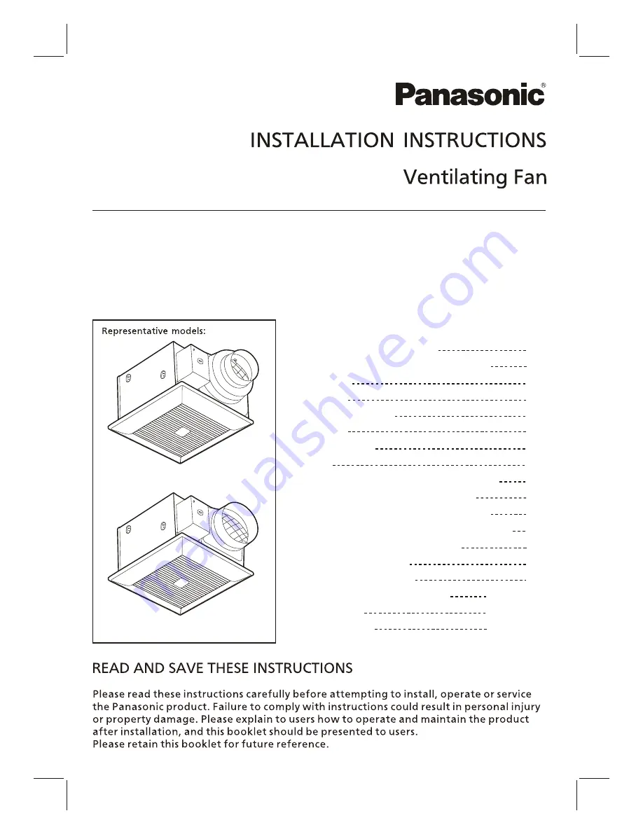
background image

FV-05-11VKS1
FV-05-11VK1
FV-11-15VK1

Model  No.

Thank  you  for  purchasing  this  Panasonic  product.

FV-05-11VKS1    FV-05-11VK1

FV-11-15VK1

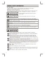
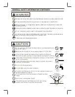
GENERAL SAFETY INFORMATION

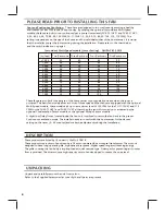
PLEASE READ PRIOR TO INSTALLING THIS FAN

DESCRIPTION

UNPACKING

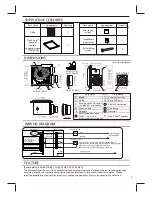
SUPPLIED ACCESSORIES
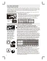
DIMENSIONS

WIRING DIAGRAM

FEATURE

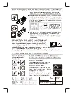
INDICATION (PLUG ‘N PLAY FUNCTION DEVICES)

DESCRIPTION FOR NIGHT LIGHT MODULE

MOTION (PLUG ‘N PLAY FUNCTION DEVICES)

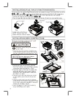
INSTALLATION (PLUG ‘N PLAY FUNCTION DEVICES)

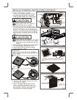
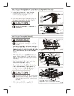
INSTALLATION (NEW CONSTRUCTION)

INSTALLATION (RETROFIT)

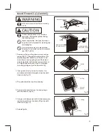
MAINTENANCE (CLEANING)

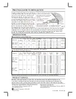
PRACTICAL GUIDE TO INSTALLATION

SPECIFICATIONS

PRODUCT SERVICE

Contents

2-3

4

4

4

5

5

5

5-6

6-7

7

7

8

8-10

10

11

BACK COVER

BACK COVER

BACK COVER

Summary of Contents for FV-05-11VKS1

Page 1: ...PLIED ACCESSORIES DIMENSIONS WIRING DIAGRAM FEATURE INDICATION PLUG N PLAY FUNCTION DEVICES DESCRIPTION FOR NIGHT LIGHT MODULE MOTION PLUG N PLAY FUNCTION DEVICES INSTALLATION PLUG N PLAY FUNCTION DEV...

Page 2: ...d shower enclosures For Your Safety To reduce the risk of injury loss of life electric shock fire malfunction and damage to equipment or property always observe the following safety precautions Explan...

Page 3: ...r dedicated parts such as mounting fixtures must be used if such parts are provided Do not install the unit where ducts are configured as shown in Fig A Adaptor CAUTION Canada only Not to be installed...

Page 4: ...100 105 110 Two Bedrooms Three Bedrooms Four Bedrooms Five Bedrooms DESCRIPTION These products are listed by UL under UL file No E78414 These products use a sirocco fan driven by a DC motor powered b...

Page 5: ...30 2 4 1 3 5 7 8 TM Flex Z Fast bracket with 4 tapping screws ST4 2X20 1 Multi Speed module FV 05 11VKS1 only other models not included Plug N Play module slot Plug N Play module slot Power switch Fan...

Page 6: ...efore returning to the lower speed setting chosen on the CFM dial Pick A Flow CFM Multi Speed Air volume CFM 50 110 110 130 150 0 0 0 0 0 0 40 40 40 60 60 60 40 60 60 80 80 80 40 70 80 100 100 100 40...

Page 7: ...FF 20 minutes time delay FV MSVK1 only Fan active At low speed When motion or excess humidity is detected fan runs at high speed Remains running at high speed until the delay time has passed FV CSVK1...

Page 8: ...ody by removing the machine screw M4X6 before installation Fig 1 IMPORTANT Remove the tape from damper and adaptor before installation As shown below The fan position between joists from 16 to 24 on c...

Page 9: ...age 5 Follow all the local electrical safety codes as well as the National Electrical Code NEC Using UL approved wire nuts connect house power wires to ventilating fan wires Fig 5 INSTALLATION NEW CON...

Page 10: ...e step 1 4 5 on page 8 and step 7 on page 9 Before connect the circular duct to the adaptor should pull down the circular duct from the ceiling Disconnect power source before working on unit 5 Follow...

Page 11: ...FV MSVK1 or FV NLVK1 Pull down the mounting spring that without lead wire passed side and remove motion sensor or LED night light as shown in Fig 16 Squeeze mounting spring and pull down carefully Dis...

Page 12: ...mbination Our efficient cool running motors and our LED lighting unit do not create enough ambient heat to be subjected to these limitations HVI Certified performance based on HVI Procedures 915 916 a...

Reviews: