background image

These instructions contain information on operating the scanner. Before reading these instructions, please read 
the installation manual enclosed with this unit.

Please carefully read these instructions and the enclosed installation manual. Keep all documentation in a safe 
place for future reference.

 Model No.    

KV-S4085CL / KV-S4085CW
KV-S4065CL / KV-S4065CW

Operating Manual

High Speed Color Scanner

Summary of Contents for KV-S4065CL - Sf Clr Duplex 65PPM USB 2.0 Lgl 300PG...

Page 1: ...ns please read the installation manual enclosed with this unit Please carefully read these instructions and the enclosed installation manual Keep all documentation in a safe place for future reference...

Page 2: ...n scanning A4 size paper in portrait orientation Support for High efficiency Scanning Jobs This scanner has a Stapled document detection function which can automatically detect stapled documents and t...

Page 3: ...ing system hereafter Windows Windows 2000 refers to the Microsoft Windows 2000 operating system hereafter Windows 2000 Windows XP refers to the Microsoft Windows XP operating system hereafter Windows...

Page 4: ...ows 2000 Windows XP Windows Vista Interface USB 2 0 Memory 1 GB or higher Hard Disk 5 GB or more free space is required Note The above system requirements may not satisfy the requirements of all opera...

Page 5: ...tion manual may cause harmful interference to radio communications Operation of this equipment in a residential area is likely to cause harmful interference in which case the user will be required to...

Page 6: ...me Size 27 Scanning Documents with Pages of Different Sizes 32 Using Control Sheets 39 About Printing Control Sheets 40 Changing the Scan Background Color 41 Switching the Reference Plate 41 Care and...

Page 7: ...Troubleshooting 77 Shading Adjustment 80 Repacking Instructions 81 Specifications 83 Index 85 Operating Manual 7...

Page 8: ...unspecified cur rent rating the unit or plug may emit smoke or become hot to the touch When you operate this product the power outlet should be near the product and easily accessible To ensure safe o...

Page 9: ...e Operating the contaminated unit can cause fire or electric shock Do not open covers and do not attempt to repair the unit yourself Contact your dealer for service Do not alter the unit or modify any...

Page 10: ...it by both side grips Dropping the unit can cause injury and damage to the unit Operating Safeguards If the unit falls down or gets damaged turn the unit off and unplug the power cord Otherwise it ma...

Page 11: ...YOUR PREMISES THEN THE FUSE SHOULD BE REMOVED AND THE PLUG CUT OFF AND DISPOSED OF SAFELY THERE IS DANGER OF SEVERE ELECTRICAL SHOCK IF THE CUT OFF PLUG IS INSERTED INTO ANY 13 AMP SOCKET If a new plu...

Page 12: ...the CD ROM Roller Cleaning Paper Keep the roller cleaning paper out of reach of small children Do not store the roller cleaning paper in direct sunlight or in a place with a temperature over 40 C 104...

Page 13: ...nstru ments This list is not inclusive and no liability is assumed for either its completeness or accuracy In case of doubt contact your legal counsel Notice Install your machine near a supervised are...

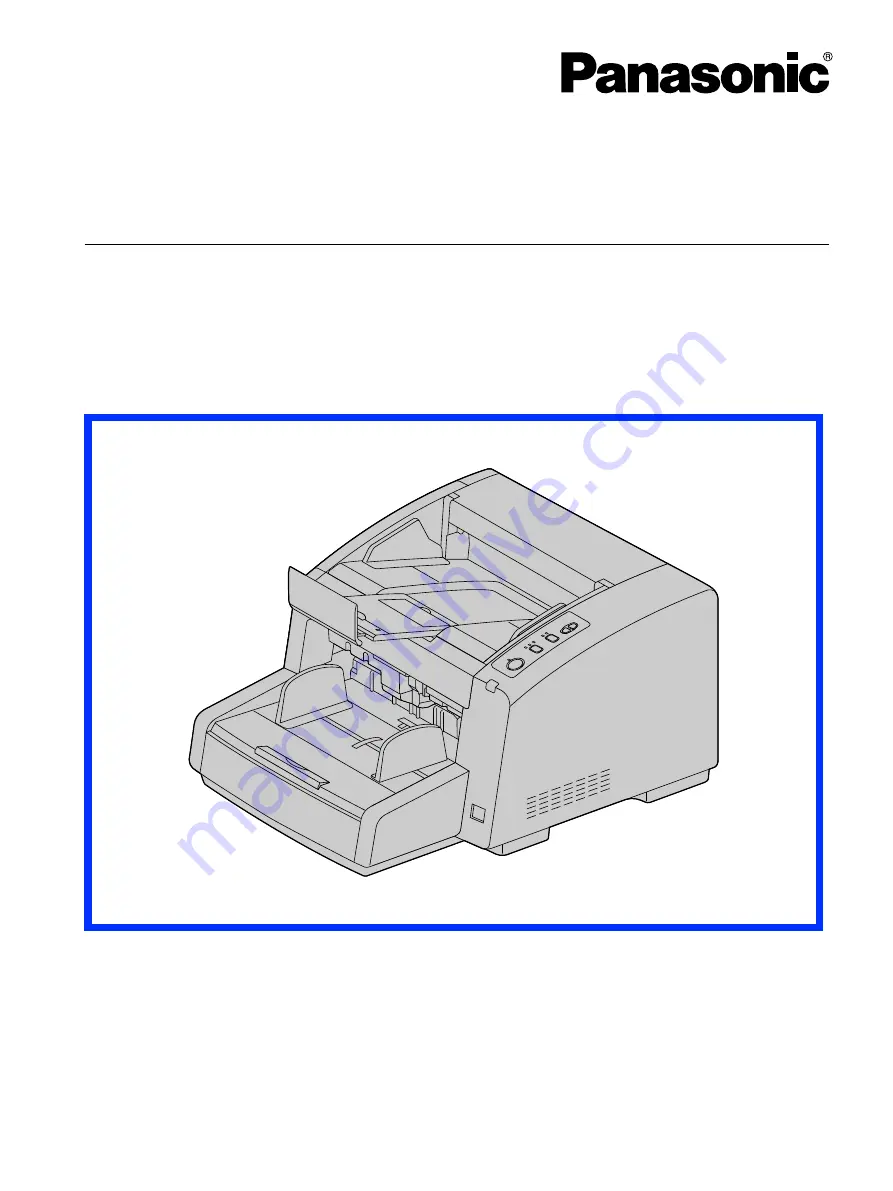
Page 14: ...opper 6 Document guides 7 Hopper 8 Hopper extension tray 9 Control Panel For details refer to Control Panel page 16 10 Error indicator Lights when an error occurs For details refer to About Status Ind...

Page 15: ...imprinter unit sold separately or ink cartridge For details on installing an imprinter refer to Post imprinter page 69 3 Fan exhaust vent 4 AC inlet 5 Power cord Plugs may vary in shape depending on c...

Page 16: ...auto feeding or manual feeding 3 Paper thickness key Thickness Changes the paper thickness mode according to the document type See Changing the Paper Thickness Mode page 24 4 Start Stop key Start Sto...

Page 17: ...r Ready Shows the scanner s status For details see About Status Indicators page 18 1 For details on Manual Feed Mode refer to the RTIV Reference Manual or PIE Reference Manual Operating Manual 17 Loca...

Page 18: ...y indicator Green 2 Error indicator Red Status ON OFF Ready ON Blink Slow Caution 1 OFF ON Error 1 Blink Slow OFF Sleep Blink Slow Blink Slow Caution 1 Sleep Blink Fast OFF Warming up 1 Check the stat...

Page 19: ...Turning on the Scanner Power 1 Set the power switch 1 of the scanner to ON 2 1 The ready indicator 2 lights green Operating Manual 19 O p e r a t i o n Operation...

Page 20: ...oadable on the hopper Page thick ness g m 20 5 lbs 40 11 lbs 50 13 lbs 64 17 lbs 75 20 lbs 80 21 lbs 90 24 lbs 104 28 lbs 157 42 lbs 209 56 lbs Max num ber of sheets 500 350 320 300 250 240 210 180 12...

Page 21: ...ng direction For documents with mixed page sizes and thicknesses Document thickness The ratio of page thickness between the thickest and thinnest pages must be less than 1 5 Document size The ratio of...

Page 22: ...ink Non rectangular or irregularly shaped paper Notes about documents for scanning Depending on the paper type scanning results may be poor when you scan unacceptable documents or even documents that...

Page 23: ...to the amount of paper so that the hopper is at the same level as the feeder Setting the hopper position beforehand will shorten the scanning time Press the hopper key or to change the hopper positio...

Page 24: ...hen to use Thin 20 50 g m 5 13 lbs When scanning thin paper or paper with a rough surface such as NCR paper Normal 50 157 g m 13 42 lbs When scanning normal paper such as copier paper Thick 157 209 g...

Page 25: ...h Closed Front side Exit tray Opened Back side Straight path tray Note When scanning documents with a thickness of 0 2 0 6 mm 7 9 23 6 mils such as folded documents set to straight path If you are usi...

Page 26: ...before scanning Failing to do so can damage the unit document or both Curled documents may cause a paper jam or damaging the document therefore set the document flat before scanning When scanning impo...

Page 27: ...cuments that have been stapled together or stacked together as in a file folder will need to be separated A Fan the stack of documents to separate all the edges B Hold both ends and bend the documents...

Page 28: ...they stop 1 2 Notice The height of the documents should not exceed the limit mark 2 on the document guide This may cause a paper jam or skewing The scanning width is different for the KV S4065CL KV S...

Page 29: ...1 When scanning long sheets of paper Pull out the hopper extension tray 2 from the hopper 2 Note After placing the document on the hopper if you push the Start Stop key the hopper will rise to a posi...

Page 30: ...nd raise the exit stopper 2 1 2 Note If you scan documents with the exit stopper 2 down documents may jam at the exit When scanning long sheets of paper Adjust the exit stopper 3 and extension sub tra...

Page 31: ...of the document Scanning direction Document 5 6 When scanning thin documents Slightly raise the exit sub stopper 7 The documents will exit smoothly since there is a smaller step at the exit 7 8 Open y...

Page 32: ...on the control panel to select auto feeding 2 Fan the documents Documents that have been stapled together or stacked together as in a file folder will need to be separated A Fan the stack of document...

Page 33: ...3 Align the document pages along one side 2 2 2 2 4 Completely spread apart the document guides 1 1 Operating Manual 33 Operation...

Page 34: ...orrectly 2 1 2 3 Notice The height of the documents should not exceed the limit mark 3 on the document guide This may cause a paper jam or skew Depending on the types of paper the document may not be...

Page 35: ...ce slide the left document guide 2 to where you will place the left edge of the document 2 2 1 7 While keeping the left document guide 1 in place slide the right document guide 2 to match the width of...

Page 36: ...r if you push the Start Stop key the hopper will rise to a position where pages can immediately start being fed 8 Slide the exit guides 1 to match the width of the document guides 2 and raise the exit...

Page 37: ...he largest document page 4 5 2 When scanning short sheets of paper When scanning documents like the one shown in the figure below fully raise the exit sub stopper 6 and adjust the extension sub tray 7...

Page 38: ...step at the exit 8 9 Open your scanning application 1 and scan the documents 1 The software RTIV and QuickScan Pro demo included with the scanner can be used for scanning the documents Note By fully s...

Page 39: ...ROM B S i m p l e x A Documents Control sheet Code Documents Control sheet functions Simplex Duplex Binary 256 level gray Color Dynamic Threshold Dither Error diffusion Function 1 9 Separation Sheet...

Page 40: ...IE Reference Manual Printing control sheets Note In order to print control sheets Adobe Reader must been installed on your computer Refer to the instruction manual for your printer for details about c...

Page 41: ...to the same color If the front and rear settings are different then documents will not be scanned correctly Anytime the background color is changed from its previous setting you must perform shading...

Page 42: ...3 Move the reference plate lever R 1 and the reference plate lever F 2 1 2 Move the levers to the color you want to change the background to White Black 42 Operating Manual Operation...

Page 43: ...4 Close the front door Push both sides of the front door down slowly until it clicks into place 5 Set the power switch of the scanner to ON Operating Manual 43 Operation...

Page 44: ...o the following procedure CAUTION The image sensor covers may be very hot after scanning a lot of documents Removed the jammed sheet after the image sensor covers temperature has cooled 1 Pull the fro...

Page 45: ...side of the scanner towards the front When a paper jam occurs at the exit slot Pull the jammed paper from the exit slot 1 towards the front 1 3 Close the front door Push both sides of the front door d...

Page 46: ...ves or surfactants for cleaning the outside of the scanner Clean the scanner at least once a month 1 Set the power switch 1 of the scanner to OFF 1 2 Clean the cover with a soft cloth The document fee...

Page 47: ...3 Remove dirt and dust from the fan exhaust vent 1 with a brush 1 Operating Manual 47 Care and Maintenance...

Page 48: ...er cleaning paper 1 Notice Keep the roller cleaning paper out of reach of small children Do not store the roller cleaning paper in direct sunlight or in a place with temperature over 40 C 104 F Only u...

Page 49: ...an cause injury Notched section A Image sensor cover Straight path tray The image sensor covers may be very hot after scanning a lot of documents Clean the image sensor covers after the temperature ha...

Page 50: ...arrows in the illustration If you wipe too hard you may damage or misalign the roller For instructions on how to remove the double feed prevention roller see Replacing the Double Feed Prevention Roll...

Page 51: ...tion of Rollers 1 2 3 1 Paper feed rollers 2 Separation rollers 3 Free rollers 4 5 4 Drive rollers 5 Double feed prevention roller Left side view 6 6 Drive rollers Operating Manual 51 Care and Mainten...

Page 52: ...7 7 7 Free rollers 4 Close the front door Push both sides of the front door down slowly until it clicks into place 5 Set the power switch of the scanner to ON 52 Operating Manual Care and Maintenance...

Page 53: ...User Utility to 0 Start User Utility and in the window click the Clear Counter button 2 for After Clean Roller 1 to reset to counter to 0 For details refer to the User Utility Reference Manual 1 2 Op...

Page 54: ...ed section can cause injury Notched section A Image sensor cover Straight path tray The image sensor covers may be very hot after scanning a lot of documents Clean the image sensor covers after the te...

Page 55: ...eyor indentations 2 and blow off dirt as shown in the illustration below 1 2 Location of Sensors 5 4 4 3 6 7 3 Waiting sensor 4 Skew sensors 5 Double feed detectors For the KV S4065CL KV S4065CW there...

Page 56: ...Left side view 11 11 Paper jam sensor Location of Reflectors 12 13 12 Reflectors 13 Indentations Left side view 14 14 Indentations 56 Operating Manual Care and Maintenance...

Page 57: ...off any dirt from the slip detect sensor 2 while rotating it 2 1 5 Close the front door Push both sides of the front door down slowly until it clicks into place 6 Set the power switch of the scanner t...

Page 58: ...s text and numbers on docu ments Includes 1 ink cartridge For instructions on installation see Installing the Imprinter Unit page 67 Note To purchase replacement parts or optional units contact the st...

Page 59: ...eed Rollers and Separation Rollers WARNING Do not place the separation rollers or paper feed rollers where small children can reach them There is a danger that the rollers may be swallowed In the even...

Page 60: ...the paper feed rollers 2 and separation rollers 3 2 3 1 5 Take out the new paper feed rollers and separation rollers in the optional Roller exchange kit KV SS033 6 Align the shaft and the roller hole...

Page 61: ...d roller cover correctly If the paper feed roller cover is not closed completely when closing the front door the paper feed roller cover may break 8 Close the front door Push both sides of the front d...

Page 62: ...ion roller cover cannot be opened if the hopper is not in the Low position For details on adjusting the hopper s height see Changing the Hopper Position page 23 1 Set the power switch 1 of the scanner...

Page 63: ...s you by using the indent 1 1 4 Remove the double feed prevention roller 1 in the direction of the arrow 1 5 Take out the new double feed prevention roller in the optional Roller exchange kit KV SS033...

Page 64: ...cause double feeding or a paper jam 7 Close the double feed prevention roller cover by pushing it up in the direction indicated by the arrow Notice Be sure to close the double feed prevention roller...

Page 65: ...front door Push both sides of the front door down slowly until it clicks into place 9 Plug in the power cord and set the power switch of the scanner to ON Operating Manual 65 Replacement Parts and Opt...

Page 66: ...lity to 0 Start User Utility and in the window click the Clear Counter button 2 for After Replace Roller 1 to reset the counter to 0 For details refer to the User Utility Reference Manual 1 2 66 Opera...

Page 67: ...inter prints on the face of the document before scanning The printed material will also be scanned The post imprinter prints on the rear of the document after scanning The printed material will not be...

Page 68: ...and insert the pins 3 and 4 into the guides until they are locked by the springs 1 2 3 4 3 4 1 2 4 Connect the cable Notice Be sure to correctly match the rib with the slot prior to inserting the conn...

Page 69: ...wer switch of the scanner to ON Note For details on installing an ink cartridge refer to Installing the Ink Cartridge page 72 Post imprinter 1 Set the power switch 1 of the scanner to OFF 1 Operating...

Page 70: ...2 Open the post imprinter door 3 Connect the cable Notice Be sure to correctly match the rib with the slot prior to inserting the connector 70 Operating Manual Replacement Parts and Optional Units...

Page 71: ...and insert the pins 2 on both sides into the guides until they are locked by the springs 3 1 2 1 2 3 5 Close the post imprinter door 6 Set the power switch of the scanner to ON Note For details on in...

Page 72: ...talling the Ink Cartridge Install the ink cartridge in the imprinter 1 Set the power switch 1 of the scanner to OFF 1 2 Remove the protective tape 72 Operating Manual Replacement Parts and Optional Un...

Page 73: ...position Notice When using the pre imprinter adjust the position following the label on the scanner 4 Insert the ink cartridge into the carriage 5 Lock the ink cartridge adjustment lever 1 1 Operatin...

Page 74: ...arriage to the ink cartridge exchange position Notice When using the pre imprinter adjust the position following the label on the scanner 3 Pinch the ink cartridge adjustment lever 1 and lift it 1 4 R...

Page 75: ...n line 1 The green line 1 indicates the printing position Printing is not available in any other position 2 1 3 Adjusting the post imprinter printing position 1 Move the carriage to the desired printi...

Page 76: ...in 30 8 mm 1 2 in 16 5 mm 0 6 in Document size Document size Center Note The above figure is for when viewing the document from the front pre imprinter For the post imprinter the printing positions ar...

Page 77: ...tly Connect the USB cable correctly The software is not installed correctly Uninstall the software from the comput er and then install the software again Refer to Installing the Software in the Instal...

Page 78: ...eeding method to auto with the ADF select key Page 16 The paper thickness mode is not ap propriate for the documents Change the paper thickness mode Page 24 The document is not aligned correctly Reali...

Page 79: ...d B Page 54 The quantity distribution of light varies Adjust shading Page 80 The color of the scanned docu ment is extremely different from the original document The settings of the computer monitor a...

Page 80: ...ning shading adjustment thoroughly clean the image sensor cover F image sensor cover B conveyors in the scanning area and all rollers If you perform shading adjustment while these parts are dirty line...

Page 81: ...original carton and all of the original packing materials The scanner should be handled in the correct horizontal position Required Materials Original scanner carton and packing materials Shipping ta...

Page 82: ...canner 1 2 3 5 6 4 1 Joint 2 USB cable 3 Power cord 4 Double feed prevention roller 5 Blower 6 Drivers Utilities Manuals CD ROM Installation Manual Shading paper Roller cleaning paper 82 Operating Man...

Page 83: ...Letter Approx 160 images min A4 Approx 160 images min Simplex Letter Approx 100 pages min A4 Approx 100 pages min Duplex Letter Approx 200 images min A4 Approx 200 images min Resolution 100 600 dpi 1...

Page 84: ...AC220 240 V 0 7 A AC100 120 V 0 4 A AC220 240 V Sleep mode 4 W or less AC100 120 V 5 W or less AC220 240 V 4 W or less AC100 120 V 5 W or less AC220 240 V Operating Environment Temperature 15 30 C 59...

Page 85: ...Hard disk 4 Hopper 14 Hopper capacity 83 Hopper extension tray 14 Hopper key 16 Hopper position 23 I Image control 83 Image sensor cover B 55 Image sensor cover F 55 Imprinter unit 58 67 Ink cartridge...

Page 86: ...er jam sensor 56 Paper sensor 55 Skew sensors 55 Slip detect sensor 57 Starting sensor 55 Waiting sensor 55 Shading adjustment 80 Shading paper 82 Specifications 83 Start Stop key 16 Storage Environme...

Page 87: ...sonic U K Ltd Willoughby Road Bracknell Berkshire RG12 8FP Panasonic Marketing Europe GmbH Hagenauer Strasse 43 65203 Wiesbaden Germany For information of Compliance with EU relevant Regulatory Direct...

Reviews: