background image

Quick Reference Guide

Digital Communication Terminal


Model No.

KX-DTU100

Thank you for purchasing a Digital Communication Terminal. Please read this
manual carefully before using this product and save this manual for future use.
For more details, please refer to the manuals of the PBX.
This unit is connected to the PBX as a Digital Propriety Telephone (DPT). Refer to
the DPT settings description in your PBX manual.
 
Manuals and supporting information are provided on the Panasonic Web site at:

https://panasonic.net/cns/pcc/support/pbx/


Note

• In this manual, the suffix of each model number is omitted unless necessary.

• The illustrations may differ from the appearance of the actual product.

Summary of Contents for KX-DTU100

Page 1: ...ails please refer to the manuals of the PBX This unit is connected to the PBX as a Digital Propriety Telephone DPT Refer to the DPT settings description in your PBX manual Manuals and supporting information are provided on the Panasonic Web site at https panasonic net cns pcc support pbx Note In this manual the suffix of each model number is omitted unless necessary The illustrations may differ fr...

Page 2: ... This equipment generates uses and can radiate radio frequency energy and if not installed and used in accordance with the instructions may cause harmful interference to radio communications However there is no guarantee that interference will not occur in a particular installation If this equipment does cause harmful interference to radio or television reception which can be determined by turning...

Page 3: ...ion points in accordance with your national legislation By disposing of them correctly you will help to save valuable resources and prevent any potential negative effects on human health and the environment For more information about collection and recycling please contact your local municipality Penalties may be applicable for incorrect disposal of this waste in accordance with national legislati...

Page 4: ...Panasonic Marketing Europe GmbH Winsbergring 15 22525 Hamburg Germany For Users in the United Kingdom This unit is designed to be installed under controlled conditions of ambient temperature and a relative humidity Avoid installing the unit in damp or humid environments such as bathrooms or swimming pools 1 Important Information 4 ...

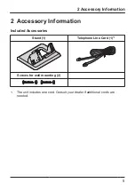
Page 5: ...cessory Information Included Accessories Stand 1 Telephone Line Cord 1 1 Screws for wall mounting 2 1 The unit includes one cord Consult your dealer if additional cords are needed 2 Accessory Information 5 ...

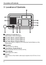
Page 6: ...e Touch Button 3 Flexible Button 5 Perform the functions assigned to the respective Flexible Buttons as One Touch Buttons Microphone Used for hands free talking Cancel Button Flexible Button 2 Stops the features that are currently running Volume Button Used to adjust the volume Pin Jack Used Connect a Push Switch cable plug It supports only 6 35 mm 1 4 in plugs 3 Location of Controls 6 ...

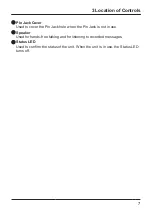
Page 7: ...Jack hole when the Pin Jack is not in use Speaker Used for hands free talking and for listening to recorded messages Status LED Used to confirm the status of the unit When the unit is in use the Status LED turns off 3 Location of Controls 7 ...

Page 8: ...ng the Call Button When making a call with the Call Button or during a conversation the call or conversation will be terminated and it will make another call Pulling out the Push Switch optional cable plug from the Pin Jack This operation performs the same function as pressing the Call Button When making a call with the Call Button or during a conversation the call or conversation will be terminat...

Page 9: ...ormation and other things Note In order to operate in this way proper PBX settings are needed However depending on the PBX settings different operation is also possible For details consult your system administrator 4 3 Adjusting the Call Volume Pressing the Volume Button If you press the Volume Up button during a conversation or playback messages the volume will increase and if you press the Volum...

Page 10: ...1 A reorder tone may be heard from the speaker Press the Cancel Button at that time then the reorder tone will stop and the unit will enter standby status Note In order to operate in this way proper PBX settings are needed However depending on the PBX settings different operation is also possible For details consult your system administrator 4 4 Terminate currently running feature 10 ...

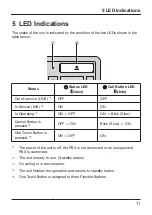
Page 11: ...ating 3 ON OFF ON Blink Slow Cancel Button is pressed 4 OFF ON Blink Slow ON One Touch Button is pressed 5 ON OFF ON 1 The power of the unit is off the PBX is not connected or an unsupported PBX is connected 2 The unit is ready to use Standby status 3 On calling or in conversation 4 The unit finishes the operation and returns to standby status 5 One Touch Button is assigned to three Flexible Butto...

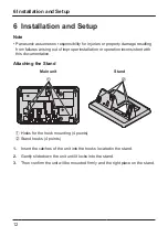
Page 12: ...n inconsistent with this documentation Attaching the Stand Main unit Stand A B Holes for the hook mounting 4 points Stand hooks 4 points 1 Insert the catches of the unit into the hooks located in the stand 2 Gently slide down the unit until it locks into the stand 3 Then confirm the unit will be mounted firmly and the right place on the stand 6 Installation and Setup 12 ...

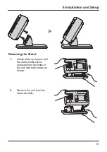
Page 13: ...oving the Stand 1 Gently slide up the unit until the stand hooks will be released from the holes of the unit with both hands as shown 2 Remove the unit from the stand carefully 6 Installation and Setup 13 ...

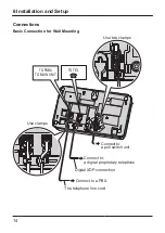
Page 14: ... Wall Mounting TO TEL TO PABX TO MAIN UNIT Use clamps Use two clamps Connect to a pull switch unit Connect to a digital proprietary telephone Connect to a PBX The telephone line cord Digital XDP connection 6 Installation and Setup 14 ...

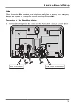
Page 15: ... or a gang box using any clamps are subject to change for smooth running of the cables Connection for the Stand Installation 1 Connect the telephone line cords and the Pull switch cable as shown below Not use clamps Use upper clamp only 6 Installation and Setup 15 ...

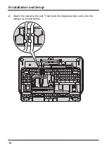
Page 16: ...2 Attach the stand to the unit Then hook the telephone line cords into the clamps as shown below 6 Installation and Setup 16 ...

Page 17: ...ach of children When the Push Switch cable plug is not connected to the Pin Jack make sure the Pin Jack is covered by the Pin Jack Cover for protection Pin Jack Cover 2 Insert the Push Switch Unit plug into the Pin Jack Use a 6 35 mm 1 4 in plug 3 Check that the plug is fully inserted all the way 6 Installation and Setup 17 ...

Page 18: ...d open the button below the terminal and insert a pair of wire coming from the Pull Switch into the terminal Cable Length Up to 50 m 164 ft 6 mm 15 64 in Stripped end of the wire 2 pin terminal Non polar Pull Switch unit In a bathroom or a next room 6 Installation and Setup 18 ...

Page 19: ...ull Switch unit A cable used to connect a pull switch to the 2 pin connector must be less than 50 m 164 ft in length We recommend to use a pair of wire cable with diameter of AWG 22 Ф0 65 mm Strip off the wire cover so that about 6 mm 15 64 in of the wire is exposed When connecting telephone line cords Ensure the cords are inserted in the grooves and are clamped to prevent damage to the connectors...

Page 20: ...the illustration below 2 Drive the screws into the wall either 83 mm 3 1 4 in or 100 mm 3 15 16 in apart and mount the unit on the wall Example 2 1 The Pull Switch cable The telephone line cord Washer Drive the screw to this point 83 mm 3 1 4 in 100 mm 3 15 16 in 7 Wall Mounting 20 ...

Page 21: ...t WALL MOUNTING TEMPLATE 1 Drive the screws into the wall as indicated 2 Hook the unit onto the screw heads 3 Make sure that the unit is attached to the wall without wobbling For KX DTU100 100 mm 3 15 16 in 83 mm 3 1 4 in 7 Wall Mounting 21 ...

Page 22: ...Note 22 ...

Page 23: ...Note 23 ...

Page 24: ...PNQX8308YA PM0916XM1037 ...

Reviews: