background image

Summary of Contents for KX-F1200

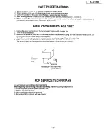
Page 1: ...s or cautions to advise non technical individuals of potential dangers in attempting to service a product Products powered by electricity should be serviced or repaired only by experienced professional technicians Any attempt to service or repair the product or products dealt with in this service information by anyone else could result in serious injury or death Panasonic l 1995 Kyushu Matsushita ...

Page 2: ...ESSORIES 4 CONNECTION 5 LOCATION OF CONTROLS 6 INSTALLATION 8 MAINTENANCE ITEM 11 TROUBLESHOOTING GUIDE 14 DISASSEMBLY INSTRUCTIONS 65 HOW TO REPLACE FLAT PACKAGE IC 76 ADJUSTMENTS 77 CIRCUIT OPERATIONS 83 CONNECTION DIAGRAM 146 PRINTED CIRCUIT BOARD 147 SCHEMATIC DIAGRAM 151 TERMINAL GUIDE OF IC S TRANSISTORS AND DIODES 173 TOOLS 175 CABINET MECHANICAL AND ELECTRICAL PARTS LOCATION 176 ACCESSORIE...

Page 3: ...e 2 Turn on the power switch 3 Measure the resistance value with an ohmmeter between the jumpered AC plug and each exposed metal cabinet part screwheads control shafts handle brackets etc Note Some exposed parts may be isolated from the chassis by design These will read infinity 4 If the measurement is outside the specified limits there is a possibility of a shock hazard The equipment should be re...

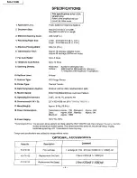
Page 4: ... Modem Speed 15 Operating Environment 6 _imensions_HX W X D 17 Mass Weight 18 Power Consumption CCD Image Sensor Thermal Transfer Modified Huffman MH Modified READ MR 9600 7200 4800 2400 bps Automatic Fallback 5 35 C 41 95 F 20 80 RH 237X420X389 mm 9 5 16 X16 9 16 X15 5 18 Approx 9 0Kg 19 8 lb Transmission Approx 17W Reception Approx 40W Copy Approx 50W Standby Approx 5W Maximum Approx 140W 19 Pow...

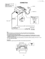
Page 5: ... other equipment When you operate this product the power outlet should be near the product and easily accessible The unit will not function during a power failure For additional equipment protection we recommend the use of a surge protector The following types are available TELESPIKE BLOK MODEL TSB TRIPPE MFG CO SPIKE BLOK MODEL SK6 0 TRIPPE MFG CO SUPER MAX PANAMAX or MPI ITW LINX If the unit con...

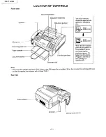
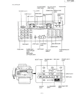
Page 6: ...NDICATOR J ___1 FILM NDICATOR 1 When the film indicator points to the position in the illustration above the remaining film produces approx 70 letter size documents Prepare a new film or film cartridge for replacement Note The visual film indicator will show FULL when a new 200 meter film is installed When the included film cartridge 30 meter roll film is installed the indicator will not show FULL...

Page 7: ... LOWER button DIRECTORY button FLASH button COPY button REDIAL PAUSE Direct call button stations MUTE button SP PHONE button FILM PAPER SAVE button lC C C O_ SELECT button O RINGER LINE 1 REC button RINGER LINE 2 button button GER 1 LINE lr_ i INE 2 C_ G REEETINc_ CHECK O l SKIP C SELECT_ MAILBOX REPEAT ALL MESSAGES MEMO 2WAY REC button button button CHECK button SKIP button ...

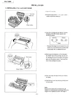
Page 8: ...s it is recommended to purchase 200 meter length film for replacement soon Green holde Green gear 4 Referring to the illustration on the left place the BACK side of the cartridge into the unit by inserting the pins on the sides of the green gears into the green holders Then lower the front of the cartridge into place 8 5 Press the head unit down firmly until it clicks into place 6 Close the top co...

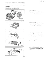
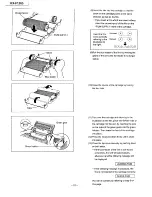
Page 9: ...ead unit 3 Take out the cartridge If you purchase a film cartridge Model no KX FA132 for replacement skip to step 11 To replace only the film go to step 4 Tab 4 Turn over the cartridge so that the PULL TAB mark is facing up 5 Unlock the tabs of the cartridge open the covers of the cartridge and take out the used film Gear_ 6 Pull out the four gears from the used film cores 7 Insert the four gears ...

Page 10: ...ge by locking the four tabs Green gear Green holder 10 11 Turn over the cartridge and referring to the illustration on the left place the BACK side of the cartridge into the unit by inserting the pins on the sides of the green gears into the green holders Then lower the front of the cartridge into place 12 Press the head unit down firmly until it clicks into place 13 Close the top cover securely b...

Page 11: ...mine the causes of equipment trouble by troubleshooting 5 Equipment repairs Repair or replace the defective parts and take appropriate measures at this stage to ensure that the problem does not recur 6 Confirm normal operation of the equipment After completing the repairs conduct copying self testing and communications testing to confirm that the equipment opel ates normally 7 Record keeping Make ...

Page 12: ...nfirm operation of sensors If the mirror and lens are dirty clean it with a dry soft cloth Exchange the part Check the tightness of screws on all parts 5 LED Array See page 13 6 Sensors See pages 47 49 Mirrors and Lens Abnormal wear and tear or loose ness of parts 7 8 2 2 MAINTENANCE CYCLE No Items 1 Separation Roller Ref No 98 2 Separation Rubber Ref No 48 3 Feed Roller Ref No 97 178 4 Target Gla...

Page 13: ...d surely by pushing down on both ends 6 Connect the power cord and telephone line cord 3 2 CLEANING THE THERMAL HEAD If dirty patterns or black bands appear on a copied or received document clean the thermal head Thermal Do not push the black cover 1 Disconnect the power cord and the telephone line cord 2 Open the top cover 3 Press the green button on the right marked PUSH and lift up the head uni...

Page 14: ...CTIONS 18 3 COMMUNICATION ERROR FUNCTIONS 20 4 REMOTE PROGRAMMING 29 5 SERVICE HINTS 33 6 GENERAL 34 7 DEFECTIVE FACSIMILE SECTION 40 8 DEFECTIVE TAM INTERFACE SECTION 59 9 DEFECTIVE ITS SECTION 60 10 DEFECTIVE OPERATION GRILLE SECTION 61 11 DEFECTIVE SWITCHING POWER SUPPLY SECTION 61 14 ...

Page 15: ... Functions are accessed by entering their code changing the appropriate value then pressing the SET key The test Functions are accessed by entering their code and pressing the key listed on the menu While programming to cancel any entry press the STOP key 1 2 OPERATION FLOW User mode _ 1 TEST mode_ PRINT mode prints out the list to confirm the I f user programmable _ 2 SET mode i _ set values Prog...

Page 16: ... 34 EXTENSION COPY 35 COPY REDUCTION 36 RX REDUCTION 39 LCD COHTRAST _41 REMOTE FAX ACTIUATION CODE 42 MESSAGE ALERT 43 REC TIME ALERT 45 BUSY MESSAGE 46 RINGER MODE _50 MAIL BOX ALERT 51 BOXI PASSWORD 52 BOX2 PASSUORD 53 BOX3 PASSWORD 60 COMMON PAGER 61 MAIL BOXI PAGER _62 MAIL BOX2 PAGER _65 b_IL BOY3 P_GER ID DESTINATION START TIME LINEI LINE2 LINE1 LINE2 LINE1 L INE2 _70 FAX PAGER 88 SET DEFAU...

Page 17: ... on FAX communication select Modem test Scanner test Motor test LED test LCD test Paper jam detection select KEY test CCD position adjustment value set CCD auto position adjustment Set Value X100 ms X10 ms 1 10 PPS 2 20 PPS 1 6sec 2 4sec 1 2100 HZ 2 1100 Hz I On 2 Off 1 On 2 Off 1 On 2 Off 1 On 2 Off 1 On 2 Off 1 Off 2 Phase B 3 AIIphases I See page 20 1 On 2 Off Xlmm Effective Range 001 _600 01_9...

Page 18: ...it select Time between CED and 300 bps 593 594 Overseas DIS detection select 595 596 Receive error _imRva ueset Transmit level set Transmit speed 2400 BPS fixed mode select X second X number of rings 1 On 2 Off X time 1 350msec 2 180msec 3 Off 1 On 2 Off 1 On 2 Off X msec 1 On 2 Off 1 On 2 Off X number of times X second 1 Off 2 All 3 Auto 1 75 ms 2 500 ms 3 1 sec 1 detects at the 1st time 2 detect...

Page 19: ...5 851 852 853 854 861 Sensor VOX check Printer feed test Print test pattern Top margin Left margin A4 size set 1 2 1 2 Default 16 16 Remarks The fall back starts from each speed The fall back starts from each speed Sets the tone detection mode after dialing manually Sets the tone mode in pause Sets the tone detection mode after redialing START input START input START input DTMF single tone transmi...

Page 20: ...OM CHECK SCAN CHECK LCD CHECK Service Mode Service Mode Service Mode Service Mode Service Mode Code 0 Operation after code input START Operation 1 Idle mode Press the MENU 9 0 O O x 5 5 6 buttons 2 LC DI__ I 3 Input the 2 digits Input code O0 Stop 10 For ward RX motor 01 Forward TX motor 11 Forward RX TX motor 20 Backward RX motor 02 Back ward TX motor 22 Backward RX TX motor 4 Press the start but...

Page 21: ...Po Paper Cut Sensor Pa Recording Paper Sensor Pt Paper Top Sensor Ri Ribbon Sensor LCD DISPLAY Paper inserted at the read Position Cover Open Sensor On Set Recording Paper Sensor On Sensor On MONITOR The Vox Signal When there is sound from LINE or EXT TEL Mute LED lights ON 2 1 BUTTON CODE TABLE Button Name RESOLUTION START SET LOWER COPY PAPER SAVE SP PHONE MUTE LINE 2 RCV MODE LINE 1 RCV MODE ER...

Page 22: ...MP I L M Communication was interrupted withthe STOP button Document paper is jammed No document paper Thermal head is overheated Out of thermal paper Cover is open Recording paper is jammed Transmission is finished when T1 TIMER is expired DCN is received after DCS transmission FTT is received after transmission of 2400BSP training signal No response after post message is transmitted three times R...

Page 23: ...Confirm the receiver s FAX ma chine was set to the reception mode when the previous com munication was NG DCN is received after DCS transmission Confirm the receiver s FAX ma chine J I YES word of the receiver s FAX ma chine or set the caller s pass _ machine is the out of pa _ word corresponding to the _ j er or mechanical errorj_ I receiver s and transmit the data l 1NO I YEs f_sk the receiver t...

Page 24: ...it is attributable to line condition or the receiver s machine sensitivity condition If no effect is obtained 2 Slow down the transmission start speed and transmit to the receiver again IT aoa n I _1 NO Ask the receiver to perform FAX communication from the re ceiver to the caller Check if the line is not inter rupted by noises or in the cross talk If it is not wait until the line is satisfactory ...

Page 25: ...on firm the machine condition Modem test Reler to page 20 5 J _ 3 1 _ RTN and PIN are received _ _ No response after FTT is transmitted Perform communication test us ing the LOOP simulator and check the machine reception condition I YES _6 _1 1 Check if the line is not inter rupted by noises or in the cross talk If it is not wait until the line is satisfactory for correct com munication 25 ...

Page 26: ...t the data Receive Complete NO I L No post message _ _t Decrease the RX speed 7 1 _ Ask the service section of the sender s FAX machine for ex amination YES 8 _ RTN is transmitted PIN is transmitted to PRI Q PIN is transmitted I SIow down the reception start speed and receive again NO 1 26 ...

Page 27: ...hine was set to receivable mode 9 _ Necup ion is finished when I 1 I IME is expired J Change the ring count to 1 YES Turn ON the FAX monitor func tion and have the receiver in question transmit the data again 4 I No 6 1 YES I e o 1 2f ...

Page 28: ...ll el Iraqi ibllll_5 oli u I_RSU al id L I 5 NO Ask the service section of the receiver s FAX machine for ex amination DCN is received after DIS transmission Confirm if a mechanical trouble occurred e g the caller inter rupted the transmission J Have the caller transmit the data again NO Ask the service section of the caller s FAX machine for exami nation 12 _ 300BPS error Modem error Check the ha...

Page 29: ...er to transmit the data again Confirm if a mechanical trouble occurred e g the receiver inter rupted the reception 1 Perform voice communication with the NG receiver Check if the line is not inter rupted by noises or in the cross talk If it is not wait until the line is satisfactory for correct com munication 14 _ DCN responds to post message YES Ask the receiver to set the receiver s FAX machine ...

Page 30: ...ver side being polled I YES Ask the receiver to set the Poll mode again and perform polling NO Ask the service section of the receiver s FAX machine for ex amination _R Ode m test efer to page 20 _ 16 _ Carrier is cut when image signal is received 1 Perform communication test us ing the LOOP simulator and check the machine reception condition I o _ 6 1 _ 30 ...

Page 31: ...e manual by dial keypad And presses _ set The customer s unit receives the service value He hears Pii Pii double short beeps 7 Then he can repeat from step 5 8 When he wishes to end the REMOTE PROGRAMMING MODE he replaces the handset on the cradle or the customer presses the STOP button NOTE 1 To enter the REMOTE PROGRAMMING MODE is necessary in Step 3 Because the unit can not easily enter the REM...

Page 32: ...t ul the cradle or customer press STOP key END I Press mistaken key Pii Pii Pii Press mistaken key Pii Pii Pii I REMOTE PROGRAMMING MODE Piiii Press a digits code of service function and then press _ set 1 SERVICE SETTING MODE Piiii l Press 1 3 digits value of func tion and then press _ set SETTING THE FUNCTION Pii Pii 32 ...

Page 33: ...em test 555 Scanner test 556 Motor test 557 LED test 558 LCD test 559 Paper jam detection select 561 Key test 563 CCD position adjustment value set 564 CCD auto position adjustment _ 713 Rr_k o _ _elect Set Value mm dd yy hh mm up to 30 digits up to 20 digits ERROR ON OFF 1 to 4 rings 1 2 3 4 rings TOLL SAVER RINGER OFF VOX 1 MIN OUT IN OFF ON OFF ON OFF ON OFF ON OFF AUTO LINE l LINE 2 AUTO LINE ...

Page 34: ...elect Receive speed select Manual tone detect Pause tone detect Redial tone detect CPC mode Power ON film feed T1 timer Busy message out Speaker Bus message out LINE 1 Sensor VOX check Printer feed test Print test pattern print Set Value T00 99 001 999 01 99 1 ON 2 OFF 01 99 1 350msec 2 180msec 3 OFF 1 ON 2 OFF 1 ON 2 OFF 0 999 msec 1 ON 2 OFF 1 ON 2 OFF 00 99 001 999 1 OFF 2 ALL 3 AUTO 1 75 2 500...

Page 35: ...TOM 1 Defective general ITS operation 2 Other defective operation CURE l KX F1200 Defective solder IC1 on analog board or check tor solder short Defective solder on IC404 or 10405 check for solder short Refer to page 41 35 ...

Page 36: ...y any charactors I Display Refer to page 37 I Err ne us Display I Check reset circuit Refer to page 38 I Check clock pulse I Refer to page 39 I 1 I Check bus line I Refer to page 40 I l Check key scan and input Refer to page 40 Check IC404 Refer to page Check IC405 J 41 J I I Replace IC401 or IC402 or IC403 36 ...

Page 37: ...upply section Refer to page 63 OK Check connection between CN401 402 403 Digital board and CN4 Analog board Insert the connector and cable exactly into CN401 402 403 and CN4 OK Check the voltage between pin 3 and 4 of CN4 Analog board 4 85 V _ V_ 5 35 V NG I Replace the connector cable for CN4 I Analog board OK Go to next page Check reset circuit 37 ...

Page 38: ...8 of IC401 4 5 V YES Replace IC401 I Is the voltage at pin 66 of IC404 4 5 V NL NO Replace IC409 Is the voltage at pin 36 of IC41 4 5 V YES Re0aceC404 Replace IC417 NU YES Is the voltage at pin 67 of IC405 4 5 V NO I Replace IC405 J YES ts t_e _o ta o_e at p_r_ 5 o_ C4Q8 4 5 YES END NO I Replace IC408 38 ...

Page 39: ... Replace R593 or C526 LC502 C434 R635 YES Is the frequency at pin 81 of IC404 12 MHz ZIj I v NO YES Check the frequency at pin 68 of IC405 again J OK I Replace IC405 Is the frequency at pin 28 of IC401 16 MHz YES Check the frequency at pin 56 of IC404 3 5 V T 24 MHz _L I OK I I NO NG l I Replace IC404 END Replace R748 R747 X404 C751 C752 IC404 39 ...

Page 40: ...al board and IC1 Analog board Or replace some of these ICs END Note 5 Check key scan and input Is the waveform at pins 1 3 7 8 11 14 43 44 of IC301 Operation board shown below Y_I I i YES NO Check connection between CN404 Digital board and CN301 Operation board OK NG END Check the solder at pins 132 136 of IC404 Insert the cable exactly into CN301 OK Replace IC404 40 ...

Page 41: ...89 92 99 101 104 of IC404 4 5 Vp p YES Reset Is the voltage at a pin 66 of IC404 4 5 V YES NO NO j Check the solder of pins 84 89 92 99 101 104 of IC404 Check the solder of these pins Is the voltage at pins 37 38 64 65 of IC404 0V YES NO I Check the solder of these pins J END 41 ...

Page 42: ...en one I I page Check motor gears one way clutch and E ring for one way clutch 1 Check separation rubber and separation spring J Press down READ SEN SOR gently and release it to be come up immedi ately Clean up separation roller using dump clothes Rubbing alcohol Replace separation roller with new one NG r Need to service Check sensor is in stalled properly No obstacle such as a piece of plastic i...

Page 43: ...nt image on RX side has many er rors OK Increase 596 Transmit level set from 10 dBm to 5 dBm or some or Decrease 596 Trans mit level set from 10 dBm to 12 dBm or some OK Decrease 596 Trans mit level set from 10 dBm to 15 dBm or some 1 Ask RX party increase a parameter of RX error line value to more than No available I YES J Check modem TX level J Change 594 Oversea DIS detection to Detect at the 2...

Page 44: ...sender below change I i Increase 596 Transmit i level set YES I Which mode 1 NO I ncrease 593 time between CED 300bps to some value Error code No 68 Echo I_ _o_e I _1 FAX r ing count is 2 3 or 4 YES Change FAX ring count to1 YES I NO I 1 I_ r_ _e I I ANS FAX ring count is 2 3 or 4 J I YES J Change ANS FAX ring count to 1 J I Decrease 596 Transmit level set from 10dBm to 12dBm or some 1 Change 718 ...

Page 45: ...message OUT OF PAPER Even paper is installed prop erly CHECK COVER LCD massage l Even Top cover is closed Even no jamming LCD Check paper sensor Check the platen roller and shaft holders are installed properly Check cover switch a fin to press down the cover switch Check sensor lever Check sensor on sensor board Replace sensor 45 ...

Page 46: ... PSP01 oKI NG I Set film cartridge NO I Does any Error message display I YES I heck cover open sensor SW1 I Is the recording paper jammed N_ YES I Remove the jammed recording paper I Is a beep tone emitted when a docu ment is inserted YES I Press Copy button I l Continued to 2 J NO r Check document sensor PI302 Refer to page 48 46 ...

Page 47: ...902 Check paper out sensor PS905 I l Perform the printer test OK END I Check read section Refer to page 51 Check thermal head Refer to page 55 Note 1 Check cover open sensor SWl L Is the voltage at pin 47 of IC401 4 5 V when cover close and 0 V when cover open NO YES Check the motion ot sensor lever I OK END NG Replace lever Check the solder at pin 47 of IC401 OK I NG k l Replace SWl Replace IC401...

Page 48: ...en no document set OK Check the solder at Q303 Check the solder at PI302 OK Replace IC301 f I Replace PI302 Note 3 Check read position sensor PI301 Operation Board Check the voltage at pin 15 of IC301 4 5 V when document set 0 V when no document set OK Check the solder at Q303 OK Repair Replace IC301 Check the solder at PI301 48 ...

Page 49: ...paper set 4 5 V when recording paper out OK NG _ heck the connection between CN414 and CN904 Replace PS904 I J L Check the voltage at pin 45 of IC401 0 V when recording paper set 4 5 V when recording paper out OK ChecklC401 NG t heck the solder at pin 45 of IC401 and R564 R510 C580o ReplacelC401 49 ...

Page 50: ...YES Check foreign matter in gear damaged gear and motor I END I YES l OK I Replace Q410 YL_ Is the phase signal from pins 16 17 20 22 of IC404 output NO I YES i Is the voltage at pin 8 of IC407 Repair _ NO END eac L I NO I No YEsYES I I Is the phase tsignal from pins 23 27 of IC404 output Is the solder at pins 23 27 of 1C404 OK I YES I Replace 1C406 Is the voltage at pin 1 of IC407 less than 2 V Y...

Page 51: ... Is the voltage at base of Q401 0 6 0 7 V YES Is the voltage at Icollector of Q401 0V l YES Check the pattern between Q401 and CN406 NO NO I 1 Replace IC401 1 Check the solder of R411 R412 Replace Q401 J Clean the surface of the glass I Copy a document 1o_ END J NG Check the connection between CN406 and LED lamp I 1 K Is the voltage at pin 1 of CN406 24 V Replace LED lamp l I i I Repair the connec...

Page 52: ...S I heck switching power supply section Refer to page 63 l heck the waveform of CCD and read section Refer to page 53 t ake out cable from CN405 and t___IG check the amplitude at pins 2 5 of CN405 4 5 Vp p OK I Check CCD board Refer to page 56 Check the solder at pins 12 15 of IC404 I OK Replace IC404 I I 52 ...

Page 53: ...ing V CH1 0 5 V div CH2 5 V div DC couple CHOP mode H 1 msec div Trigger CH2 SLOPE Probe point GND Test point AG CH1 Test point VID CH2 Test point FTG Waveform _ CHI CCD signal CH2 FTG GATE signal trigger Note This waveform will be shown when the CCD reads the white plate ot document cover ...

Page 54: ...V div AC couple 1 V div DC couple GND _ 1 Air II i A i A V_VVVVVVVVV_ i0 about 2 Vp p _ 2 _VVVVVV _ about 1 Vp p about 3 6 V 1 8V NO _ 1 _ 2 CH1 probe point 10801 pin 1 CCD Board CN801 pin 7 CCD Board 10404 pin 3 AMON Digital Board_ 54 ...

Page 55: ... Check the cable of CN407 and CN301 OK OK 1 Replace thermal head J NO Is the voltage at pin 6 of IC401 4 5 V YES I heck switching power supply section Refer to page 63 Take out CN407 and check the amplitude again Check the solder at pin 6 of IC401 and Q407 NG Z K Check the solder at pins 29 32 of IC404 and pin 34 of IC417 NG Replace IC404 or IC417 OK I Check the solder R420 R421 C405 R422 C406 C40...

Page 56: ...t CN801 Dboard and check the amplitude at pins 2 5 of CN401 Digital board 4 5 Vp p Check the short at pins 2 5 of CN80 CCD board Check the solder at pins 12 15 of IC404 Digital board END Check the waveform at pin 1 of IC801 CCD board Refer to page 54 OK Replace Q801 Q802 CCD board or per form CCD adjust NG I __1 K Check R801 804 Check R801 804 OK I OK Replace IC404 NG Replace R801 R804 CCD board R...

Page 57: ...to page 20 1 I Is the four signal at Tip Ring output NO Is the signal at pin 44 of IC405 output I NO t ls the voltage at pin 5 NO oflC4132 5V YES I Check the solder at I pin 73 of IC404 Replace IC405 I Select 462Hz YE_S Check the trace between pin 44 of IC405 and Tip Ring Check the trace between pin 1 of T1 and pin 48 of IC405 Disconnect loop simulator Is the siganl at pin 48 of IC405 462Hz input ...

Page 58: ...led manually if possible this unit be switched to FAX by__ _button when the greeting is heard and then the START button should be pushed for FAX communication Another possibility is entry of two pauses at the end of the auto dial number of the transmission side in this way the start time for the count can be delayed by 2 pauses about 10sec Note For short greeting recording the greeting button must...

Page 59: ...al should be 2100Hz 1 and 2 will become ON Then the echo of the DIS signal output afterwards may be received and FAX1 may execute errone ous operation preventing start of communication Countermeasure B In service mode the CED signal frequency is set to 1100 Hz code No 520 or the time setting between the CED signal and the DIS signal is set from 75msec to 500msec in service mode code No 593 This is...

Page 60: ...ency is set to 1100Hz service mode code No 520 7 6 UNIT CAN COPY BUT THE TRANSMISSION AND RECEPTION IMAGE IS INCORRECT LONG DISTANCE OR INTERNATIONAL COMMUNICATION OPERATION This depends widely on the transmission and reception capability of the other FAX set and the line conditions The countermeasures for this set are shown below 1 Transmission Operation The transmitting speed is set to 4800BPS s...

Page 61: ...he caller on hook this unit can detect the following 4 signal types A CPC pulse B Dial tone or other continuous tones C Silence D Cyclic signals A Check CPC DETECTION CIRCUIT B C D Check VOX DETECTION CIRCUIT 8 5 REMOTE CONTROL DOES NOT WORK RESPONSE IS POOR The following are considered as the cause of no remote reception A Is the ID code the same as set on the unit B The send signal interferes wi...

Page 62: ...ge 125 NO I Remove PC2 or PC6 1 Is the voltage at pin 97 or 98 of IC1 change between high level low level INO YES i Replace PC2 I R13or PC6 R43 Check IC1 9 3 NO RING TONE Check bell detection circuit Refer to page 125 J Is the bell detection circuit OK I YES Does a ring tone signal appear at pin 44 of IC404 Digital Board I YES _ Replace IC404 I Following the ITS section Monitor circuit refer to pa...

Page 63: ...OK Repair I YES NO ReplaceLCD I i_ YES END I _ _ J Check IC301 j 11 DEFECTIVE SWITCHING POWER SUPPLY SECTION 11 1 NO OPERATION It is necessary that power supply is connected to analog board and digital board to test the power supply I sFI01 open I NO YES _ls Q101 short Is D101 short _ls D103 short is Rl15 open YES YES I YES I YES Is D201 shorted YES molt _ Is PC101 shorted I _ IslC2Olshorted IYEs ...

Page 64: ...V 12 V ANIJ 12 V ARE NOT OUTPUT I s R204 R206 open or 5 12 12 V not output NO r 12 V not output YEs 5 V not output J YES No 1 12 V not output 1 YES YES Is Q202 shorted YES IsQ203 shorted YES q Is D207shorted YES Is D204 shorted YES Is D205 shorted YES Is D206 shorted YES Replace each part 64 ...

Page 65: ...tion panel Remove the 2 screws A and remove the operation panel block Remove the 7 screws B and remove the operation panel cover Remove the 5 screws C Pull out the 1 connector and remove the operation board Remove the LCD Operation Panel Block Front Lid Open Lever _ _ ReadingPlate ISeparation S Connector 65 Operation Board HOW TO CLEAN Clean the reading plat with cloth soaking in al I cohol ...

Page 66: ...KX I i 200 Ref No 2 Procedure 2 J HOW TO REMOVE THE TOP COVER 1 Remove the 2 screws A 2 Push the installing section in the direction of the arrow to remove the top cover Top Cover 66 ...

Page 67: ...d open lever to open the operation panel Open the top cover Remove the TEL No Card Remove the 3 screws A Remove the handset cradle cabinet Remove the 3 screws B Pull out the speaker connector Remove the speaker i KX FI2O6 No Card Iset Cradle Cabinet Top Cover Connectol Operation Panel Front Lid Open Lever 67 ...

Page 68: ...emove the 2 screws A and remove the thermal head cover Pull out the 2 connectors Remove the thermal head block Remove the shaft Remove the film sensor board Remove the angle from the thermal head Remove the 2 screws B of thermal head and remove the guides Top Cover Thermal Head Block rmalHead Cover Thermat Guide L Connector Film Sensor Board Shaft 68 HOW TO CLEAN Clean the printing surface oftherm...

Page 69: ...f No 5 Procedure 5 HOW TO REMOVE THE PAPER SET OUT sENSOR BOARD 1 Remove the 2 screws A 2 Pull out the connector 3 Remove the paper set out sensor board i KX F1200 Connector Paper Set Out Sensor Board 69 ...

Page 70: ...he lower cabinet l i Lower Cabinet Ref No 7 HOW TO REMOVE THE POWER SUPPLY BOARD Procedure 6 7 1 2 3 4 5 Pull out the 3 connectors Remove the 5 screws A Remove the 1 screws B Connector Remove the 2 screws C _ _ Remove the power supply board _ _r _ _ _ 4 ___ i_l _ COnnectOr _ I _ _ _ _ Connector I 70 ...

Page 71: ... motor block l l _A i I UU _ _J _t Transmission Motor Block Ref No 9 Procedure 6 9 HOW TO REMOVE THE RECEPTION MC TOR BLOCK 1 2 3 4 5 Remove the 3 screws A Remove the cover Pull out the 3 connectors _ Remove the 3 red screws B F Remove the reception motor block _ _ _u_ _ Recepti n M t r Bl ck __ r_Y j __ _ __ _ _ 71 ...

Page 72: ...VE THE ANALOG AND DIGITAL BOARDS 1 Remove the 1 screws A 2 Remove the analog board 3 Remove the 3 connectors from analog board 4 Remove the 7 connectors 5 Remove the 4 screws B 6 Remove the digital board Connectors nnector Analog Board Digital Board 72 ...

Page 73: ...Ref No 11 I I Procedure 6 9 10 11 HOW TO REMOVE THE COD UNIT 1 Remove the 2 screws A 2 Remove the CCD unit KX F1200 CCD Unit HOW TO CLEAN Clean the glass of CC unit with cloth soaking in alcohol 73 ...

Page 74: ...mission motor block 3 Remove the spacer with minus screwdriver small size as shown in following Fig A 4 Remove the roller 5 Remove the gear and spacer from roller shaft and replace roller Gear Gear Spacer Gear Separation Roller Spacer Spacer Document Feed Rollers Spacer Transmission Motor Block Spacer Fig A 74 ...

Page 75: ...Ref No 13 Procedure 6 9 10 8 7 13 2 Remove the mechanical chassis I KX i200 I hanical Chassis 75 ...

Page 76: ...fic gravity 0 863 Original flux will be replaced daily 1 Temporarily fix the FLAT PACKAGE IC by Soldering on two marked pins Temporary soldering point Accurate setting of the IC to the corresponding soldering foil is vital 2 Apply flux to the all pins of the FLAT PACKAGE IC Flux 3 Solder the specified solder in the direction of the arrow while slide the soldering iron O iron Specified solder MODIF...

Page 77: ... no feeding Position B Standard position Position C Case of multiple feeding 3 Close the lid surely by pressing down on both ends 1 2 3 CONFIRMATION OF SEPARATION SPRING Open the operation grille Check the highest level of the separation spring with the spring height tool PQZZ2F500M Please make sure that the separation spring does not touch the tool during this operation Both right and left See Fi...

Page 78: ...MENU button Press the 9 0 0 0 and w buttons Press the 5 5 and 5 buttons Notes 1 When replacingthe lens pay attentionto the markings on the lensare whiteand yellow The numberofthe CCD spacersto use differs dependingon the markingas follows Referto page 180forthe locationofthe CCD spacer 2 Install the lens so that the marking White or Yellow on it is upper side 3 Do not touch the glass face of the l...

Page 79: ... screw and CCD board fixing screw l KX 1 12UU Oscilloscope setting CH1 0 5 V div CH2 2 V div TIME 1 ms Trigger CH2 Mode AC I o L L U board Extension Cord Part No PQZZ8K18Z Never connect land AMON f CN405 __1 FTG VID O _ _ OSCILLOSCOPE To point FTG __ To point VID AG To LED array for CCD Unit DG f CN406 DIGITAL BOARD Extension cord Part No PQZZ2K12Z Lens Lens fixing screws WAVEFORM MAX for Lens MAX...

Page 80: ...hen attach on the target gla_ This is a temporary treatment You should use an instrument for this adjustment purpose if you require _ _ accurate repairment CCD Tool PQZZF5OOM White Paper ex PPC Paper WAVEFORM _ 1 2_ _U 2V 5 DOCUMENT READ START POSITION ADJUSTMENT 1 Connect AC cord 2 Copy the document and confirm the read start position of the document 3 If get out of position adjust the read posit...

Page 81: ... lOl Willie level d JJUStll_u_L iIor le o _ JuuUl re_u posJtion _djustment edge of the glass f _Tape I i I Make sure the position of and _ The edge of glass and chart should be put together then fix with tape 81 ...

Page 82: ...KX F1200 I 82 ...

Page 83: ... Control the operation panel I F Control the thermal head I F and CCD I F Excution image processing 7 Gate Array IC417 Excution image processing 8 MODEM IC405 Executes modulation and demodulation for FAX communications 9 Read Section Composed of the LED array light source CCD image sensor to read transmitting documents 10 Thermal Head Contains heating elements for dot matrix image printing 11 Moto...

Page 84: ...KX F1200 j E O3 o_ v O o B I l I 84 _ _ ec_ a o 0 ...

Page 85: ...ON 2 1 BLOCK DIAGRAM L L L O oo ZZZ 000 i if 0 cO __ _ I OJ _ rr rr o_ rr rr xO xo o_ _ o_ 1 ocr_ _70HJ_3N _ 1VOHIMBN J VOH1 IV7H1 i XNIN o ZV7 0V7 _ V 9 LV 17V gLQV 0OV _NX_ 1 1_ Q 0 _ p n 85 OmW v nn o8 I O z _o j n w WZ q 1J _o ...

Page 86: ...l I ALE TI IAD7 IT AD6 r I AD5 AD4 AD3 Pin Chip Carrier Pin Assignmets 1 Pin Bescriptions ADO AD15 Address Date A16 A23 RD WR HWR ALE RESET RAS CAS DMUX INT1 Bus input output Address Bus output Read output active Low RD indicate that the CPU wants to read date from ADO AD15 Write output active Low WR indicate that the CPU Address Data bus ADO AD7 holds valid data Write output active Low HWR indica...

Page 87: ...Z L HU I Imlr_y 16MHz A16 A23 X i KX ri200 Read Cycle A16 A23 X ADO AD15 I A0 A15 1 I D0 D15 1 ALE r RD Write Cycle X1 16MHz A16 A23 A16 A23 ADO AD15 I D0 D15 t ALE WR HWR 87 ...

Page 88: ...KX F1200 j Xl Read Write Timing RAS CAS DMVX DA0 DA9 RD WR HWR Row Address X Column Address X RAS CAS before RAS Refresh Timing CAS RAS Refresh Cycle CAS 16 2_s 88 ...

Page 89: ...G PORT ASIC IC404 INTERNAL RESISTOR SCREEN DISPOSITION SRAM 2 4 ROM IC402 The 256KB ROM EPROM orMASKROM is usedto storeprogram The addressis 000000H 03FFFFH 2 5 STATIC RAM IC403 The 32KB SRAM that is backed up with lithium battery is used This holds one touch dial automatic dial and ID etc The ad dress is 300000H 307FFFH 2 6 DYNAMIC RAM IC415 416 This DRAM is used for CPU work The address is 44000...

Page 90: ... and 8KB Fig A indicates the mapping which is used image processing Transmits the recorded data to the thermal head Controls the transmission motor which feeds the document Controls the receiving motor which feeds the recording paper Serial Interface with Operation panel I O Port Interface Exa Sensor etc This memory is built in to ASIC IC404 to be used for image processing Memory map of Image Data...

Page 91: ...j KX r i YOU z _ 8 E _ a o_ ___ _o Q X o z JZw _Z OZ_W _ I old _r7 _o n _ l I _ 0 xxx o 121 _N I if w fr O I 0 w 91 ...

Page 92: ...5 CPU IC401 ADDRESS DATA BUS AD6 CPU IC401 ADDRESS DATA BUS AD7 CPU IC401 ADDRESS DATA BUS AD8 CPU IC401 ADDRESS DATA BUS AD9 CPU IC401 ADDRESS DATA BUS AD10 CPU IC401 ADDRESS DATA BUS AD11 CPU IC401 ADDRESS DATA BUS AD12 CPU IC401 ADDRESS DATA BUS AD13 CPU IC401 ADDRESS DATA BUS AD14 CPU IC401 ADDRESS DATA BUS AD15 CPU IC401 CPU IC401 CPU IC401 CPU IC401 CPU IC401 CPU IC401 CPU IC401 LOW FIXED AD...

Page 93: ...PUT RECORDED IMAGE OUTPUT TO THERMAL HEAD CLOCK OUTPUT FOR DATA TRANSFER TO THERMAL HEAD PULSE OUTPUT FOR DATA LATCH TO THERMAL HEAD STROBE SIGNAL OUTPUT TO THERMAL HEAD STROBE SIGNAL OUTPUT TO THERMAL HEAD STROBE SIGNAL OUTPUT TO THERMAL HEAD STROBE SIGNAL OUTPUT TO THERMAL HEAD THERMAL HEAD STROBE SIGNALS POLARITY CONTROL SIGNAL TRANSFER MOTOR A PHASE TRANSFER MOTOR B PHASE TRANSFER MOTOR A PHAS...

Page 94: ...ERMISTER TEMPARATURE WATCH INPUT ANALOG PART STANDARD VOLTAGE SIGNAL OUTPUT INPUT TERMINAL IN RESISTOR POSSIBLE TO INPUT ANALOG SIGNAL MONITOR TERMINAL AiD CONVERTER S BIAS VOLTAGE OUTPUT CONNECT BYPASS CONDENSOR A C CONVERTER S ZERO STANDART VOLTAGE OUTPUT A D CONVERTER S 1 2 FULL SCALE VOLTAGE OUTPUT CONNECT BYPASS CONDENSOR A C CONVERTER S FULL SCALE VOLTAGE OUTPUT CONNECT BYPASS CONDENSOR A D ...

Page 95: ...about 72 86 92 and 100 by MODE 0 and 1 MODE0 I MODE1 o I 1 o I o 1 I 0 1 I 1 Reduction rate 100 92 86 72 The latch latches a address of high ranking byte AD8 15 in CPU IC 401 to output LA8 15 The inverter is used in the reset circuit IC417 Block Diagram I S from THCLK IC404 1 THDAT 3 from CPU MODE0 2 LATI0 7 8 ALE 1 INVI0 3 4 tReduced circuit Latch L 1 1 8 4 NEWTHCLK _ to CN407 NEWTHDAT Thermal he...

Page 96: ... 18 I O 39 17 Initializing reduced circuit Clock input Latch input Data input Reduced clock output Reduced data output Reduction rate Explanation setting MODE0 0 MOVE1 1 100 MODE0 0 MOVE1 0 92 MODE0 1 MOVEI 0 86 MODE0 I MOVE1 1 72 Mode setting Latch input 0 Latch input 1 Latch input 2 Latch input 3 Latch input 4 Latch input 5 Latch input 6 Latch input 7 Latch gate input Latch output 0 Latch output...

Page 97: ...the system is reset completely This is done to prevent partial resetting and system runaway during power fluctuation Timing Chart 5 4 3 JJ 4 2 _Fv_ 4 3 J about 175 ms j_ bout 175 ms Jl i i i i i i 2 When pin 3 of the IC409 becomes low level it will prohibit the RAM IC403 from changing data The RAM IC403 go into the backup mode when they are backed up by the lithium battery 5V C701 7 IC409 Circuit ...

Page 98: ...he watchdo ___g__Eor occurs pin 114 of the gate array 10404 becomes low level The terminal of WDERR signal is connected to the reset line so WDERR signal works as the reset signal Circuit Diagram GATE ARRAY IC404 l I 5V Ic40g 22 _6 RAMCS CPU I0401 MODEM 10405 IC417 21 10417 _9_ IC4O3 RAM LOG BOARD PORT IC I p_ON BOARD 98 ...

Page 99: ... the RAM IC403 and RTC IC408 At this time the voltage at pin 28 of the RAM and pin 8 of the RTC are 5 V When the power switch is turned OFF the BATT supplies the power to the RAM and RTC through the JMP1 R701 and IC409 At the time the voltage at pin 28 of the RAM and pin 8 of the RTC are about 2 5 V When the power switch is OFF and the voltage of 15 V goes down the Reset IC IC409 outputs the reset...

Page 100: ...al interface The serial interface signal is produced in the software and uutput Iro_ I L purl of CPU iC 401 These timings are shown below CS SCK SlO J Read Timing about 60ps Read c o mmand 64 I IIII _ Clock Calender data L Write Timing CS SCK SlO J _1 19 L L L L l_l LI 64 _ iolo11 x xlxlx I Write command 111 t Clock Calender data L 100 ...

Page 101: ...efore this circuit can keep the thermal head at an even temperature in order to stabilize the printing density and prevent the head from being overheated Circuit Diagram TO THERMALHEAD IH HEAD I J R420 1 29 I 30 31 32 3_ NEWTHDAT THDAT 142 33 NEWTHCLKI0417 THCLK 144 35 THLAT h43 _ 34 8 C405 C407 STB1 STB2 STB3 STB4 THDAT THCLK THLAT ADSEL1 AIN2 10404 Timing Chart I Effective signal ref LEVEL CLAMP...

Page 102: ...Process ing Section and after finishing of draft s information s image processing white is regarded as 0 and black is regarded as 1 and by way of routes _ and _ they are stored in RAM 4 White Black data stored as above description 3 by way of routes _ and _ it is inputted to P S converter White Black data converted to serial data in P S converter is inputted to Thermal Head by way of route _ and i...

Page 103: ... 200 Block Diagram IC404 IU41bt411o RAM IC402 ROM IC401 CPU 6YSTI M BUS __ MODEM I IC405 IMAGE PROCESSING SECTION P S CONVERTER ANALOG SIGNAL I CD IMAGE SENSOR PROCESSING SECTION THERMAL HEAD NCU TEL LINE 103 ...

Page 104: ...ot increment all the shift register become filled with data and a latch pulse is emitted to each IC from IC404 pin 34 THLAT With this latch pulse all the contents of shift registers are latched to the latch registers Thereafter through the addition of strobe from the IC404 pins 29 30 31 32 only dot of location of black 1 among latched data activates driver and current passes to heat emitting body ...

Page 105: ...ADSEL1_ c4o5 I I c4o7 _ I1 _ 1 c o8 _ R421 I C406 T fR422 440 140 HERMAL HEAD CN2 _ _ __i_i_ __I _ _ _ _ H o s_ l H o_o _ o 1 11 y i I _N_03 i i Timing Chart CN407 _ NEWTHDAT PRINT DATA I 3 0 psecx1728 5 184 msec NEXT LINE PRINT DATA I I _WT O_ _ ___ _ O_sec THLAT C STB1 _ STB2 _H I 1 f 3 0 msoc 1728 pcs _ _ _ r_ 320 pcs IF 3 0 seo about 1 8 msec at 25 C L_J 1728 pcs TEMPERATURE OF THERMAL HEAD __...

Page 106: ... START COPY button is pressed IC401 pin4 goesto a highleveland Q401 is turnedON whichmakes CN406 pin 2 go to a low leveland the voltageappliedto the LEDarrayto turnonthe LED F1 F2 FR and FTG signalsare outputto the CCD boardto drivethe CCD imagesensor Therefore whenthe LED is turnedON the VIDEO analogimagesignal is outputfrom the CCD boardto CN405 pin 7 F1 F2 FR VIDEO CCD Scanner Timing Chart 1 Do...

Page 107: ...g pulses are output form gate array IC404 pins 23 26 causing driver IC406 pins 10 13 drives TX Motor Coil The motor coil is energized sequentially in 2 phase increments which causes a 1 step rotation Rotation of 1 step feeds 0 13mm of recording paper or document paper Timing chart is below TM0 TM1 TM2 TM3 Stepping Motor Timing Chart 2 2 Phase 1 2 Phase 1 217 sec r 1 217 sec Stepping Motor Drive Mo...

Page 108: ...r is stopped long time about 70 80 msec at receive mode gate array IC404 pin 27 become_ low lewl a d driver IC406 pin 14 becomes high level This causes Q403 to also go OFF and instead of 24 V 5 V is supplied through D602 so that the motor is held in place When the system is in the stand by mode all of the motor drive transistor is OFF Therefore the motor current is OFF 108 ...

Page 109: ...r IC of current drive type The inside of chopper IC and the peripheral circuit diagram are shown below Circuit Diagram IC407 Motor _ Crrent Control L 24V B _ II C606 R631 R640 IC404 RXE R621 CPU P32 R627 CPU P33 _ II C607 iR632 5V R628 R629 CN409 o o o o RX Motor _633 PG Power GND Motor t Phase Pattern IC404 RM0 IC404 RM1 IC404 RM2 IC404 RM3 O INA O INB 0vl o R622_ I I R624_ c o 0604 j bove motor ...

Page 110: ... 217 pps 217 pps MAX 217 pps MAX 217 pps or 326 pps List Print Stand by 2 2 All phase current off 217 pps Stopped _ Paper feed include film feed at cover close non printing area feed feed for top of page error feed etc Motor Current Control Motor Drive CPU Port Drive Pattern P 32 P 33 RXE RM0 RM1 RM2 RM3 High level Unused High level refer to timing chert refer to timing chert refer to timing chert...

Page 111: ...ocument Read Position Paper Set Paper Top Paper Out Film End Mainly LCD Error Message at sensor fail CHECK DOCUMENTJ REMOVE DOCUMENTJ rOUT OF PAPERJ CHECK CASSETTEJ PAPER JAMMEDJ FILE EMPTYJ CHECK COVERJ _ See TEST FUNCTION SENSOR CHECK SECTION for sensor test c f 815 and 801 of Service Mode test Sensor Location PI301 Document readpositionsensor PI302 DocumentSensor Coversensor Cover PS901 Filmend...

Page 112: ...R_0 I 45 o c T Digital P C B CPU IC401 P34 P74 Phototransistor Signal IC401 45 pin Set Recording Paper ON Low level No Recording Paper OFF High level Paper Out Sensor JAM Sensor PS905 When the recording paper is jammed the shelter plate shuts the sensor light the phototransistor becomes OFF and the input signal of IC401 406 CPU becomes high level Usually the shelter plate passes the sensor light t...

Page 113: ...s low level SHELTER PLATE Psg 21 i i i i i B i i i i i i i CN902 i i i i Sensor P C B 1 2 3 5V CN413 _ R566 IC401 44 P73 52 P34 Digital P C B Phototransistor Signal IC401 44 pin Paper Pass OFF High level No Paper ON Low level All interrupt Sensor LED current is controlled by IC401 52 pin e g PS904 PS902 PS905 Cover Sensor SW1 When the upper cabinet is closed SWl becomes OFF and IC401 47 pin goes t...

Page 114: ...nable High Disable Operation Board Phototransistor Signal IC301 15 pin Out of the Read Position ON Low level At the Read Position OFF High level Document Sensor PI302 When a document is seen the shelter plate shuts the sensor light the phototransistor becomes OFF and the input signal of IC301 19 pin Operation becomes high level When there is no document the shelter plate passes the sensor light th...

Page 115: ...odem IC405 has hardwarewhichsendsand detectsallof the necessarysig nalsfor FAX communication It can be controlledby writingcommandsfrom theCPU IC401 to the registerinthe modem IC405 Thismodem IC405 alsosendsDTMF signals generatesa calltone fromthe speaker and detects a busy toneand dial tones Overview of Facsimile Communication Procedures ITU T CCITT Recommendation 1 ON ITU T CCITT International T...

Page 116: ...ission of Time I Transmission Time I I Control Time I Image Transmission Time I I H ld Time I Transmission time consists of the following Control time This is time at the start of transmission when functions at the sending and receiving sides are confirmed transmission mode is established and transmission and reception are synchronized Image transmission time This is the time required for transmis...

Page 117: ...1 TCF CFR Training 2 Image RTCInf rmati n EOP MCF DCN Bell Detection Notifies of capacity of receiving unit e g recording paper width transmission speed Check the receive preparation and line condition Receive preparation OK Record Start Record Stop Reception OK Disconnect Control signals are comprised mainly of 8 bit identification signals and the data signals added to them Data signals are added...

Page 118: ...th capability A4 297 mm Unlimited A4 297 mm and B4 364 mm Invalid Receiver T 4 operation Data signalling rate 2400 bit s V 27 ter 4800 bitJs V 27 ter 9600 bit s V 29 7200 bitJs V 29 Vertical resolution 7 7 line mm Two dimensional coding Recording width 1728 picture elements along scan line length of 215 mm 4 1 2432 picture elements along scan line length of 303 mm 4 1 and 2048 picture elements alo...

Page 119: ...rved for G4 capability on PSTN Extend field Recording width Recording width indicated by bits 17 18 Recording width indicated by this field bit information Middle 1216 elements of 1728 picture elements Middle 864 elements of 1728 picture elements Invalid Invalid Extend field Note 1 Standard facsimile units conforming to T 2 must have the following capability Index of cooperation IOC 264 Note 2 Sta...

Page 120: ...case of operator call from receiver 2 Redundancy Compression Process Coding Mode This set uses one dimensional MH format a Document b Part of document I Basic Technique of Facsimile Facsimile ___ c Run length and image signals equivalent to b d Codification of c according to MH formula Black 4 2 4 2 8 3 Run length Modified Huffman MH Cede Code for Code for White Line Black Line o 00110101 00oo11o1...

Page 121: ...NCU Section R30 _ C29 IC14 6 7 R20 T1 Line1 _Line2 is the same IC7 IC15 T2 Line2 2 Facsimile Reception The analog image data which is received from the telephone line passes through the NCU section and enters pin 45 of the modem IC5 The signals that enter pin 45 of the modem IC5 are demodulated in the board to digital image signals then placed on the data bus In this case the image signals from th...

Page 122: ...I_X F1200 I E a o O 8 a n I Q uJ 5 ILl Z 0 I 3 u I o 0 z TT I I I _ _ I 0 I_ T I I I I m__t 1 00_ I I I _d _ _ I I L_ _ I _ 4_ _ _ _I _ x _T2 o x x n S n v O e Q _o CO 5 i _J 122 ...

Page 123: ... hands free and handset circuits in 1 chip The handset and microphone are connected to this circuit At the time of hands free operation the SP output is outputted after passage through the power amplifier IC12 and the key tone and the pulse dial monitor tone output from IC404 Digital Board and IC1 Analog Board are given as input to this IC and become the monitor tone at the time of hands free hand...

Page 124: ...KX F1200 J E o 0 i5 O o C o o LU Z _1 LU Z J Z I X rr t I _b O Z 0 Lo q r b 1 3 Z _ D 0 I I I I OO G GI __ W J w _w rn rn l 0c 0 n 0 D n_ w I a l r7 124 ...

Page 125: ...ine1 Signal waveform of each section are indicated below Signal low level section input to pin 76 of gate array ICl are read out at CPU and judged as bell Between Tip and Ring Line1 about150V Between PC1 1 and 2 vov 1 5V PCl 4 Gate Array IC1 76 Line1 Tip L1 C1 PC1 2 1 R1 L2 Ring _Line2 is the same as above 6 4 PULSE DIAL CIRCUIT 1 Circuit Operation ex Line1 In OFF HOOK Condition the photocoupler P...

Page 126: ...smission signal given as input to IC14 pin 6 is amplified to about 20dB it is outputted form pin 7 of IC14 and it is transmitted to T1 via R20 Without R27 R25 C23 the transmission signal would return completely to the reception amplifier via R21 Here the signal output from IC14 pin 7 passes through R27 R23 IC23 and enters the amplifier IC14 pin 3 a sig nal with the reverse phase of the transmissio...

Page 127: ...0 1 0 1 0 0 1 0 0 1 1 0 0 0 1 0 0 0 0 1 Control Output from NCU CPC L1 1_2 L1 DCN L2 0 0 0 0 1 0 0 I I I I 0 I 1 High Level 5V 0 Low Level 0V 6 8 CONFERENCE When using handset or speaker phone conference tripartite conference is possible Turning RLY3 ON sets up the signal circuit and it is valid tripartite conference among KX F1200 Line1 and Line2 The larger loss makes the lower sound between Line...

Page 128: ...KX F1200 1111311 o I 128 ...

Page 129: ...LINE2 RX F TE TX I TAM OGM F I BUSY OGM _ IMODEM IX NC I Block Diagram 64 bit SHIFT REGISTER I _ PS IC1 58 LATOH IC1 61 64 bit DATA LATCH J _ CLK IC1 62 DATA IC1 63 E IN1 57 49 S41 833 sg S1 I IN2 58 850 42 34 10 2 i IN3 _ 61 53 45 837 S13 85 T i 62 54 846 838 14 6 IN4 __ _ I I 63 855 47 39 15 ST INS qb _ I S64 56 48 40 16 88 V V V _ V V __ OUTIO Timing Chart DAfA CLOCK LATCH PS D1 D2 D3 D4 D5 D64...

Page 130: ...M ICM OGM ICM TEL TEL BUSY BUSY SP SP SP H S SP H S SP TAM TAM OGM OGM Phone Phone Phone Phone Phone CO NVER CONVER CONFER TEL TEL TEL TEL TAM TAM TAM TAM 2WAY 2WAY BUSY BUSY SATIONSATION ENCE DTMF DTMF DTMF DTMF REC REC OGM OGM S01 S02 so5 S06 so7 S08 S09 10 s13 14 s_5 s_6 33 834 37 38 39 40 41 S42 45 46 S47 48 49 50 53 54 55 56 57 58 s6_ 62 63 64 130 ...

Page 131: ...e appropriatesignals ON and OFF The attenuator controlalsodetectsthe levelof thevolumecontrolto automatically adjustfor changingambientcondi tions Transmission Signal Path The input signal from the microphone is sent through the circuit via the following path MIC Cl10 IC2 13 MIC AMP SW4 TX ATT 27 R160 _ R161 C122 IC18 2 1 C125 IC3 7 _ 15 R29 C28 IC14 6 7 R20 T1 Line1 16 J R59 C58 IC15 6 7 R50 T2 L...

Page 132: ...58 IC15 6 7 R50 T2 Line2 3 Ring Tone Low IC405 44 Digital Board 0N2 9 R211 R208 0156 R206 IC12 4 5 8 Speaker 4 Alarm Beep Keytone IC405 43 Digital Board CN2 10 R209 High IC11 9 8 Beep Keytone R207 C155 R205 IC12 4 5 8 Speaker Alarm _ ICll 4 3 IC2 Control Table Handset Mode Speakerphone Mode t Other 0 Low Level 0V Communication Transmission Mute Dial Communication Transmission Mute Dial 1 High Leve...

Page 133: ...al Middle High 3 step Switch transistor Q16 Q17 ON OFF Concerning control please refer to the table SP Phone RX Low _ High 8 step Switch analog SW IC9 ON OFF Concerning control please refer to the table Handset SP Phone Electronic Volume Control Table High Middle Normal Loud Quiet 8 7 6 5 4 3 2 1 VOL1 0 0 1 0 1 0 1 0 1 0 1 VOL2 0 1 0 0 0 1 1 1 1 1 0 VOL3 VOL4 0 0 0 0 1 1 0 1 0 0 0 0 0 0 1 1 8 6 DT...

Page 134: ...KX F1200 j __ 1 X E IO1 l l 1 o i3 CM uJ la c D _ r I I 0 Z _ _ a I 1 1 o _ 0 7 Z Z o o h F _ _ 121 134 rr o e_ 0 F oo o_ I o I i wE_ _ _ O30 II 1_ A __ ...

Page 135: ...if it is less than 15V J 2 Circuit operation 1 Settings Line1 CO mode Line1 T R 48V _ R63 _ ZD9 _ O7 _ Q8 _ PC11 _ INUSE L1 ON ON OFF OFF High II IParallel Tel ON HOOKI Line1 T R 16V R63 4 ZD9 Q7 Q8 POll INUSE L1 OFF OFF ON ON Low II IParallel Tel OFF HOOKI 2 Settings Line2 PBX mode Line2 T R 24V R70 PC10 ZD12 Q9 Q10 PC12 INUSE L2 ON ON ON OFF OFF High II A B L2 High _ IParallel Tel ON HOOKI Line2...

Page 136: ...o the digital TAM unit as the following path Reset signal is inputted by reset circuit the signal of Bout 2 is controlled by L Battery CN11 _ D20 R285 Q27 _ R283 D TAM When Back up is necessary Bout 1 is controlled by H depending on I01 Situation Bout 1 Bout 2 Power source ON No message in TAM 0 1 Power source ON Message in TAM 1 1 Power source OFF 0 0 1 Hight Level 0 Low Level Battery voltage det...

Page 137: ...C178 IC21 2 _ 1 R244 R250 _ C182 IC20 2 1 3184 R252 IC12 4 8 5 _ Speaker 4 OGM MEMO ICM to TEL Line ex Line1 D TAM UNIT ON9 5 R224 IC8 4 5 _ C164 _ R219 R220 R217 R218 IC19 3 1 R213 C131 _ R170 IC18 6 7 C129 IC3 8 15 NCU Section Line1 TEL Line Liner 5 vox The VOX circuit is the circuit for discrimination of tone or no tone IC5 pin 2 is Low Level with tone and hight level with no tone The role of t...

Page 138: ...is generated voice synthesizer plays the words from word list There is only one pattern of message as follows Hello no one is available to take your call now and our machine is busy on another call please call back in a few minutes l hank you Normally this message is played when receiving call in TAM or FAX mode during one line is in use Also the above message is output to the speaker in service m...

Page 139: ...a P 0 o T L K r i _uL pJeo_ igl B OI UOll 139 ...

Page 140: ...ns such as speech Recording Playback Tone detecting and Line Monitoring The DSP system comprises of following The Digital Signal Processor which includes the firmware implemented functions The Codec IC702 which is used as the analog I O interface The Audio grade RAM IC703 which is used for stored voice messages 1 Host i Processor IC401 DSP IC701 Analog I O _ i IC702 I i ARAM I IC703 Audio In Audio...

Page 141: ...FLASH 304 3 305 2 306 KIN1 307 ONE TOUCH 6 RINGER 1 308 ONE TOUCH 2 309 REDIAL PAUSE 310 6 311 5 t 312 4 KIN2 313 ONE TOUCH 7 GREET REC S314 ONE TOUCH 3 GRE SELECT 315 MUTE 316 9 317 8 318 7 u KIN3 319 DNE TOUCH 8 ALL MESSAG 320 ONE TOUCH 4 REPEAT 321 SP PHONE 322 S323 0 324 KIN4 325 DIRECTRY 326 ERASE 327 LINE 1 328 STOP 329 COPY 330 VOL A KIN5 346 MAIL BOX 331 RECEIVE MODE LINE 2 332 LINE 2 333 ...

Page 142: ...rs Consequently in this set the timing mainly positive clock is generated by the LCD interface circuitry of the gate array IC301 Circuit Diagram DB4 DB7 LCD E CONTROLLER DRIVER RS R W OSC1 OSC2 IC391 VCC V1 V2 V3 V4 V5 GND 1 D4 D 7 ENABLE q RESET 11 R W 9 _ 5V I I LCD CO Module Chip On Glass ON THE OPERATION BOARD IC301 P37 ED3 P36 ED2 Timing Chart R W E DB4 DB7 X DATA m X Density Light 2 P16 L P2...

Page 143: ... circuit through filter circuit Fitter circuit decreases noise terminal voltage and noise elec tric field strength Rectifier Circuit Input current is rectified by D101 and charge C105 to make DC voltage then supply power to converter circuit Voltage is supplied to control IC s kick on voltage through R102 and R103 Inrush current is limited by thermistor TH101 Converter circuit The converter circui...

Page 144: ...riod IL Eo L 1 d Ts 2 From equations 1 and 2 Eo d I d Ei i _dTs 1 d Ts In the actual circuit the fixed output voltage can be obtained by changing the winding ration of transformer T101 In this con verter circuit the duty ratio of ON period and OFF period of the transistor produces output In this power supply the bias winding is also built in in the transformer and the output value is one 24V outpu...

Page 145: ... check of power supply output i KX_T 2 3 _ Power Supply Board CN301 1 1 1 1 1 1 CN302 _ _ 5V o GND O 24V O 820 1 2W Q Voltage Meter _ Output range 5V 5 1V 5 24V 24 5V 4 _ 12V 12V 10 I 12V 12 5V__10 680_41 2W 24V 24 5V 4 4 7K 1 2W 145 ...

Page 146: ... 2 CN408 43 1 5 2 6 3 7 4 8 5 9 10 CN409 11 1 CN401 2 1 3 2 4 3 5 4 5 6 7 CN404 8 9 1 10 2 11 3 4 5 6 CN40 9 lOI 10 2 4 5 6 7 CN413 8 1 2 3 4 CN411 1 E CN414 2 1 2 3 4 5 0N412 I 1 c 2 3 ANALOG BOARD CN3 1 2 3 4 5 6 7 8 9 10 11 N2 1 2 3 4 5 6 7 8 9 10 11 10 11 2 1 BATTERY _EWTHDAT _EWTHCLK_ STB4 STB3 STB2 STB1 N901 RISEN 1 14 on sv I_1 zo GND I _1 _Z rr_ 903 1 n n wO 2 _0 3o JJ1 TO TEL LINE LINE 1 ...

Page 147: ...n the conductor indicates printed circuit on the back side of the printed circuit board 149 2 The circuit shown in _ on the conductor indicates printed circuit on the front side of the printed circuit board 3 3 I arcap II General II Zener II LED Cathode l Cathode Cathode Cathode Photo Diode IAnode Important safety notice The shaded area on this schematic diagram incorpo rates special features 0mpo...

Page 148: ...o ooo O0C 000 0 0 0_ PIO6b4ZA IC402 Notes 1 The circuit shown in r q on the conductor indicates printed circuit on the back side of the printed circuit board 147 2 The circuit shown in F q on the conductor indicates printed circuit on the front side of the printed circuit board 148 3 12 L ...

Page 149: ...TI0 ZO J I OV i_ _5v T LBATT J_ 150 200ms I i VSSj 26 _C4_ Ar 4ttz OV RA408_ BY U LJq_ ov ROM m655 IC402 5v 100 R6i6 LC714 lOP R709 RIC C715 t tOP 5V R6J7 10K ov C716 ZO 1 R55 _iV_ 0 BY 47K 5V 4 7K O402 RA407_ _DO i i iAl_ TPOUT C402 2 14 j 15 __ 16 j_ 11 _L 1 L TP_ TP2 TP3 TP4 TP5 rJL L M NO 0V NO OV _C OV OV 30 OV 3_ 32 5 33 O 34 Ol 35 O 36 Ol _ 37 O 3VD2 VD2 TXOU I vO2 V02 RXI_ VO2 3V02 AOU_ 3V...

Page 150: ... R20_ IDK 40 001 Ab _ L G SWFICH ICll PkAKi h _l_ b SPEAKER ON OV R2G 240K 620 22K 22K MO 1 r L_7 _ I I I 2_ Cl4 1 R28 220K OV MO 1 OV 0V C52 JGBP J R 104 1 40 047 10K I JL Ihal LL sv_ F ANSMISSION u_ SIGNAL CN5 OVA _Z 10NL 5V _ ov R209 C51 IC15 1 R50 220K OV u V OV R21 56K R51 56K 2K _ I b b4V SVD R7 _ c 2v 3L3 19 R12 C7 M0 033 _ _T_ C_5 _SVD SVD m I ACt IMILL hi 1_ I1 _ l i wl _ 2SC4155S 022 Rll...

Page 151: ...o 1 2 5 14 16 19 4 15 29 40 54 65 79 88 90 Voltage Waveform 5V 0V 5V 0V others 0V or 5V Notes 1 The circuit shown in _ on the conductor indicates printed circuit on the back side of the printed circuit board 157 2 The circuit shown in r m on the conductor indicates printed circuit on the front side of the printed circuit board 158 ...

Page 152: ...iO _ LT0i _ J_i_ _ _ _ _ _ _ _ _ _3_3_ _7_ _ I RT lil _ 44 21 I I _ e 1 1 01I c7o_ _ _ t o _ _ _ vo Notes 1 The circuitshown in _ on the conductor indicates printed circuit on the back side of the printed circuit board 159 2 BAli The circuit shown in r q on the conductor indicates printed c ircuit on the front side of the printed circuit beard I 160 ...

Page 153: ...1C801 a I _ o _ o _ _L lzJ 4 20 I_ T _ I IT I FR tj RSO _ 4A _ _0 _ R Iv _ N I_ I FTQ I ReO4 _ 100 2 e _ I _ I J v 17 o 7 NC 15 NO NC 7 _ _ _ 7 V L _J _ _ _ t 47 J_ L li 3 5 V I v F s I L 3 5 _ _ I _ 9 216ms I 1 J_ b Z b tJ V V mT_I L__F i Waveform voltage are COPY SEND CCD LED TEST mode All voltage is 0 V at standby mode COMPONENT VIEW _J 6 I_ L i L_t_ 3 ps 2 v___ II I ir 9 216 ms MEMO 161 162 ...

Page 154: ...10 u s Note When measuring the waveform on the primary circuit of the Switch Power Supply Board be sure to insulate the ground of the oscilloscope s probe from the ground of its power supply 163 D201 11 I _01 f C201 L 35V 1000 D210 z R201 R202 2 2K 18K VR201 5K R213 C202 100 0 1 IC201 R203 2 2K 30V f_ L or 50V Cycle 5 s T201 TRANS R206 56K Q203 L __40V Cycle 10 1 s 0V Q202 R204 C203 330 0 047 R212...

Page 155: ...A B C G H 1 I 2 KX F1200 KX F1200 j PRINTED CIRCUIT BOARD SWITCHING POWER SUPPLY I 5 I 6 I 7 I 8 I COMPONENT VIEW 10 i 11 CN30I I0 CN302 I PI_IOI IC201 C202 12 165 166 ...

Page 156: ...J 4 COMPONENT VIEW KX F1200 KX F1200 PRINTED CIRCUIT BOARD OPERATION BOARD 5 I 6 I 7 I 8 I 9 l BOTTOM VIEW l0 _ 11 12 B G H C E ii __ _ i R NO Waveform Pin No _3 29j JqSL_ov Voltage 0V LED ON 5V LED OFF I 167 168 ...

Page 157: ...323 _ 322 5317 316 s3 I 6 _ lo c 305 5304 5V YJ NEW CONF MESSAGES 342 341 337 S336 332 33t 327 5326 32 320 S315 314 309 308 303 302 RESOL 348 347 346 325 319 313 307 R380 IK 301 R327 R320 R325 t80 R324 R323 R322 180 A321 180 Sv 0307 5V R361 o I j F1370 I 0V SENSOR ON I 33_00 5V SENS_OFF 1 I _ _ ___ 5V 5V LED30 1 0305 R364 1 _ R365 I RED yo 330 DOCUMENT SENSOR READ PU DI I it i SENSOR LEO304 R_3A6A...

Page 158: ...X T 2C 5 t_ X T 2C 3 i SCHEMATIC DIAGRAM PRINTED CIRCUIT BOARD SENSOR I s I 6 I 7 I 8 I 9 10 I 11 PQUP 0616ZA D PAPER SET SENSOR PbgO4 PAPER OUT SENSOR PS905 PS904 _Vl _ _ r 1 PASEN 20 0 _ o 11 5V2 4 0 EXSEN B 0 NC 6_ 11 PQUP 0616Z D _t I t_Uo Z PsgoI POUPlOCBgZA COVER SENSOR CN1 COSEN _ _ BY _KP 4594 w0 12 171 172 ...

Page 159: ... oJ IIIIIIIIIIIIIIII 1 15 PQVISMA7029M PQVDS1ZB40F1 2SD1302 f Anode Calhode PQVDERA1802 MA165 5 I 80_ 31 100 1 PQVIR96DFXL 5 8 4 1 PQVlTC7W04FL PQVlS3510ACJ PQVlMC34119M PQVINJM4558M PQVIFA5311 S PQVIMM1245BF 23 AN1431T 17 16 24 2_ _ 8 32 1 PQVIS79164FU Cathode Anode RLS71 MA6D49 Anode PQVDHZS2B1 MA4051 MA4056 9 1 PQVICS10256N PQVIBA12003 z_ 33 _ 1 1 44 _ PQVlBU121020 MN53007QAF PQVTFS10KM10 2SA16...

Page 160: ...RX 1 1200 t 2SA 1309 LN21RPSLXV e Anode PQVDERA81004 Calhode MA 141WA athode Anode MA728 LN11WP22TDA 174 ...

Page 161: ...j KX F _2 00 TOOL EC11 EC13 EC12 EC4 EC7 EC3 EC8 EC1 EC5 EC7 EC2 175 ...

Page 162: ...KX F1200 1 CABINET MECHANICAL AND ELECTRICAL PARTS LOCATION 1 OPERATION PANEL SECTION 11 10 14 2O 16 21 24 25 28 42_35 41 31 43 44 5_51 47 48 176 49 ...

Page 163: ... P C B THERMAL HEAD SECTION 6O A7 77 87 109 110 67 119 171 170 118 A3 86 87 79 85 71 112 s 111 69 10 B _ 66 65 108 _ 74 73 i E1 76 88 PCB2 103 I PCB1 94 97 96 96 99 100 101 102 Lubrication _ PQZZSG3451 Grease CCD UNIT 177 PCB6 ...

Page 164: ...6 147 125 149 123 197 132 194 171 173 39 69 143 176 179 150 174 192 181 199 169 147 14 174 146 168 167_ 145 175 166 186 185 199 189 158 198 o 190 _ 191 61 162 187 _ 152 153 155 154 163 164 186 188 185 183 Lubrication YrPQZZSG3451 Grease _r I PQZZOLG425Y Grease 178 ...

Page 165: ...4 LOWER CABINET PAPER CASSETTE SECTION 220 226 24 223 229 9 229 5 229 1 229 1 179 ...

Page 166: ...KX F1200 i 5 CCD UNIT SECTION 3OO 306 PCB5 301 31 304 305 303 305 305 310 309 180 ...

Page 167: ...f No Part No _ XYN3 F8 _ XYN26 F6 _ XYC26 CF6 _ XTW3 S8M _ XTW3 U6L _ XTW3 W8P _ XTW3 S 10P _ XTW3 5L _ XTS26 8G _ XYN3 C6 Figure Ref No r Part No XTW3 U8L XTW3 S 12P XSB4 6 XWC4B XTW3 U6LR XYC3 CF14 Not Used XYN3 F16 XTB3 8G Figure l i f 181 ...

Page 168: ...KX F1200 j ACCESSORIES AND PACKING MATERIALS A4 A5 A12 A6 A13 P10 A7 All f FILM CARTRIDGE A2 A3 A5 t A8 A1 P5 t P4 ACCESSORY BOX P3 t P6 182 ...

Page 169: ...RD PANEL GRILLE OPERATION BUTTON VOLUME SPACER VOLUME BUTTON COVER A LED COVER B LED BUTTON DIAL BUTTON SP PHONE BUTTON STOP COPY 5UT t O_ STAP 3 1 1 1 1 1 1 2 1 I I I I I I I I I I I BUTTON HELP 1 IBUTTON ONE TOUCH 1 PLASTIC PARTS ONE TOUCH BuI rON SHEE 1 LCD UNIT 1 GUIDE LCD UNIT 1 3ONNECTOR LEAD 10P 1 Refer to the simplified manual cover I for other areas lef No 0 1 2 3 4 5 6 7 8 9 0 1 2 3 4 5 ...

Page 170: ... 1 1 1 1 2 1 1 1 1 1 1 1 1 1 1 1 1 1 1 1 1 1 2 2 5 1 2 2 1 1 1 2 1 2 6 1 1 2 1 2 2 2 1 1 2 1 1 1 3 1 1 1 1 1 2 2 1 1 1 1 1 Refer to the simplified manual Icover for other areas i Ref No 168 169 170 171 172 173 174 175 176 177 178 179 180 181 182 183 184 185 186 187 188 189 190 191 192 193 194 195 196 197 198 199 220 221 222 223 224 225 226 227 229 229 1 229 2 229 3 229 4 229 5 229 6 229 7 229 8 22...

Page 171: ...SHION INK FILM PROTECTION COVER SET DIGITAL BOARD PARTS DIGITAL BOARD ASS Y RTL ICs IC IC IC IC IC IC IC IC IC IC IC IC IC IC IC TRANSISTORS S S 1 1 O411 425 1 C426 1 0427 1 C430 1 C434 2 1 C501 1 C502 C503 C504 C505 C506 1 C507 C508 G509 C510 1 C511 1 C513 1 C514 1 C515 1 C516 1 C518 1 C519 1 1 C520 C521 1 C522 1 C523 1 C526 1 C527 1 C528 1 C530 PQCUVl E104MD PQCUV H 180JC PQCUVl H330JC PQCUV 1E ...

Page 172: ...1 i 1 st 1 S 1 S 1 S 1 S 1 S 1 S 1 S 1 S 1 1 1 S 1 2 1 1 S 1 S 2 1 1 8 2 4 1 1 1 1 1 1 1 1 1 1 4 1 1 1 5 1 1 1 1 1 1 1 1 1 1 Heler to the simpIilied nlaNuul L ovu for other areas Ref No R436 R437 R440 R442 R443 R444 R452 R454 R455 R456 45_ R460 467 R470 473 R474 47_ R476 R477 47_ R480 R501 R502 R503 R504 R505 R506 R507 R508 R509 R510 R511 R512 _513 _514 _517 _518 _553 554 _557 _558 559 R561 562 _5...

Page 173: ...VIS80732S IC IC18 19 PQVlNJM4558M IC IC20 PQVtNJM4558M IC21 PQVlNJM4558M IC22 PQVINJM4558M IC IC IC TRANSISTORS Q1 2SA1627 TRANSISTOR SI Q2 2SD1819A TRANSISTOR SI or 2SC4155S Q3 2SC2235 TRANSISTOR SI Q4 2SA1627 TRANSISTOR SI Q5 2SD1819A TRANSISTOR SI or 2SC4155S Q6 2SC2235 TRANSISTOR SI Q7 8 9 2SD1819A TRANSISTOR SI or 2SC4155S Q10 2SD1819A TRANSISTOR SI or 2SC4155S Q11 2SD1302 TRANSISTOR SI Q12 P...

Page 174: ...S 1 S 1 S 1 S 1 1 S 1 1 S 1 S 1 S 1 1 1 S 1 S 1 2 2 1 Refer to the simplified manual cover for other areas I Ref No I PartNo Part Name Description 092 C93 C94 C95 C96 97 C98 C99 C100 C101 C102 C103 C104 C105 C107 C109 Cl10 ICl12 Cl14 C115 C116 ic117 C119 C120 C121 C122 C123 C124 C125 C126 C127 C128 C129 C131 C132 C133 O134 O135 0136 C137 C138 C139 C140 C141 C142 C 43 C144 C146 C147 C148 C149 C150 ...

Page 175: ...HOTO COUPLER _HOTO COUPLER kS PHOTO COUPLER _S S 1 S 1 1 1 S 1 1 1 1 1 t S 1 1 1 1 S 1 1 1 S 1 S 1 S 1 2 S 2 1 S 1 S 1 S 1 S 1 S 1 S 1 S 4 1 S 1 8 1 1 1 8 1 2 1 S 1 1 1 1 S 1 S 1 S 1 8 1 3 S 3 1 1 1 1 2 1 3 1 1 1 I KX F1200 Refer to the simplified manual cover for other areas Ref No Part No Part Name Description J1 8 9 10 J25 L1 3 Ll1 14 L15 16 R1 _2 R3 _4 _5 _6 17 _8 _10 111 t12 _13 _14 _15 I _16...

Page 176: ...154 ERJ3GEYJ823 ERJ3GEYJ683 ERJ3GEYJ101 47K 150K 82K 68K 100 1 1 1 1 1 Ref No I Part No 165 IERJ3GEYJ473 166 IERJ3GEYJ101 167 168 IERJ3GEYJ473 170 IERJ3GEYJ104 171 174 IERJ3GEYJ222 172 173 IERJ3GEYJ562 _174 IERJ3GEYJ222 _175 IERJ3GEYJ470 176 IERJ3GEYJ472 t177 IERJ3GEYJ331 H78 179 IERJ3GEYJ102 R180 I ERJ3GEYJ102 R181 I ERJ3GEYJ563 R182 I ERJ3GEYJ224 R183 I ERJ3GEYJ335 R184 I ERJ3GEYJ474 R185 I ERJ3...

Page 177: ...WITCHES PUSH SWITCH LIDE SWITCH tRANSFORMERS FRANSFORMER tk TRANSFORMER Ak TRANSFORMER _ _THER HOOK SW SPACER CERAMICFILTER CERAMIC FILTER Pcs 1 1 1 1 1 1 1 1 1 1 1 1 1 1 1 1 4 1 1 1 1 1 1 1 1 1 1 1 1 1 1 1 1 1 2 1 1 2 1 1 1 1 1 1 2 1 1 1 2 1 1 1 1 I Refer to the simplified manual Icover I for other areas Ro NoI P o Pa Name Oesc ptiooI Pc s I I PQLP10159M MN53007QAF PQVISN7H138S PQVTDTCl14EU PQVTD...

Page 178: ...202 R807 PQ4RlOXJ242 R808 PQ4R10XJ682 R809 PQ4R10XJ180 R810 PQ4R10XJ132 R811 812 PQ4R10XJ161 CCD BOARD ASS Y RTL Ic CCDBOARDASS Y RTL TRANSISTORS TRANSISTOR SI S 2 or 2SA1576R 2SA1602F 2SA1603F TRANSISTOR SI or 2SC4155R S 1 CONNECTOR CONNECTOR 8P CAPACITORS 470 0 1 RESISTORS 0 0 100 330 100 2K 2 4K 6 8K 18 1 3K 160 8 R815 R816 R817 R819 S 1 1 VR801 2 S 3 4 PCB6 6 2 10 IC10t 7 IC20t 1 Q101 PQ4RlOXJ...

Page 179: ... 1 1 S 1 S 1 S 1 S 1 S 1 S 1 S 1 S 1 S 1 S 1 S 1 S 1 1 s 2 1 1 1 PHOTO ELECTRIC TRANSDUCER PHOTO COUPLER S Refer to the simplified manual cover for other areas Part Name Description Pa_ No PQRRT8DllF2 EVNDJAA03B53 ERZC10DK471 ERZV10DK182U ERZC10DK751U Ref No TH101 VR201 Z101 Z102 Z104 _HERMISTOR THERMISTOR VARIABLE RESISTOR SEMI FIXED RESISTOR 5K B VARISTORS VARISTOR VARISTOR VARISTOR DIGITAL TAM ...

Page 180: ...K8Z EC14 PQZZ2K7Z PQZZ2F500M PQZZF500M EXTENSION CORD 2P EXTENSION CORD 8P EXTENSION CORD 2P EXTENSION CORD 3P EXTENSION CORD 3P EXTENSION CORD 4P EXTENSION CORD 5P EXTENSION CORD 6P EXTENSION CORD 6P EXTENSION CORD 8P EXTENSION CORD 2P EXTENSION CORD lOP EXTENSION CORD 11P EXTENSION CORD 2P SEPARATION SPRING HEINGHT TOOl CCD TOOL Notes 1 Tools and Extension Cords Ref No EC1 EC2 are necessities fo...

Reviews: