background image

©

1999 Kyushu Matsushita Electric Co., Ltd. All

rights

reserved.

Unauthorized

copying

and

distribution is a violation of law.

KX-F206TW

(for Taiwan)

PARSONAL FACSIMILE

Please file and use this manual together with the service manual for Model No. KX-FT21RS, Order
No.KM79911336C3. This Service Manual indicates the main differences between; Original KX-FT21RS and
KX-F206TW.

ORDER NO. KM79911347A3

Summary of Contents for KX-F206TW

Page 1: ...bution is a violation of law KX F206TW for Taiwan PARSONAL FACSIMILE Please file and use this manual together with the service manual for Model No KX FT21RS Order No KM79911336C3 This Service Manual indicates the main differences between Original KX FT21RS and KX F206TW ORDER NO KM79911347A3 ...

Page 2: ... resistance value with an ohmmeter between the jumpered AC plug and each exposed metal cabinet part screw heads control shafts bottom frame etc Note Some exposed parts may be isolated from the chassis by design These will read infinity 4 If the measurement is outside the specified limits there is a possibility of a shock hazard The equipment should be repaired and rechecked before it is returned t...

Page 3: ...dified Huffman MH Modified READ MR Modem Speed 9 600 7 200 4 800 2 400 bps Automatic Fallback Operating Environment 5 C 35 C 41 F 95 F 45 85 RH Relative Humidity Dimensions H W D 122 mm 338 mm 240 mm 4 13 16 13 5 16 9 7 16 Mass Weight Approx 2 5 kg 5 5 lb Power Consumption Standby Approx 6 0 W Transmission Approx 16 W Reception Approx 22 W When receiving the CCITT No 1 Test Chart Copy Approx 22 W ...

Page 4: ...1 3 LOCATION OF CONTROLS 1 3 1 CONTROL PANEL Change from original page 9 1 11 2 CONTROL PANEL 4 KX F206TW ...

Page 5: ...1 4 CONNECTIONS Change from original page 10 1 12 CONNECTIONS NOTE When you operate this products the power outlet should be near the product and easily accessible 5 KX F206TW ...

Page 6: ... Document feed position adjustment value set 01 99 step 50 OK 550 Memory clear Press START NG 551 ROM check Press START NG 553 Monitor on FAX communication select 1 OFF 2 P B 3 ALL OFF OK 554 Modem test Press START NG 555 Scanner test Press START NG 556 Motor test Press START NG 557 LED test Press START NG 558 LCD test Press START NG 559 Document jam detection select 1 ON 2 OFF ON OK 561 Key test ...

Page 7: ...rnal report 1 START OK 996 Journal 3 1 START OK 999 Transmit service list 1 START OK OK Can set the value by the remote programming feature or print a list NG Cannot set the value Note Note Refer to 2 4 4 SERVICE FUNCTION TABLE for descriptions of the individual codes For example the 004 Transmission report mode set value 1 ERROR 2 ON 3 OFF number corresponds to the number dialled 7 KX F206TW ...

Page 8: ...or example power supply lightning surge voltage test withstanding voltage test intentional short circuit test etc Caution If you find a melted fuse in the unit don t turn the power on without repairing the unit first Except for the fuse If you do the fuse will melt again and the unit has not been repaired The problem exists somewhere else In most cases our experience the symptom is that nothing is...

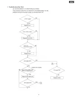
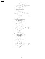
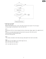
Page 9: ...2 Troubleshooting Flow Chart 9 KX F206TW ...

Page 10: ...10 KX F206TW ...

Page 11: ...amage expands to the peripheral circuit of Q101 This is due to a very high voltage through the Gate circuit which is composed of R105 Q102 and D107 You should change all of the parts listed as follows F101 Q101 R105 Q102 D107 D201 If D201 is broken the oscillation circuit in the power supply cannot operate Check it with an electric tester D204 If D204 shorts the voltage feedback circuit is almost ...

Page 12: ...an example of the SYSTEM SETUP LIST the unit prints out Change from original pages 75 2 4 3 USER MODE The list below is an example of the SYSTEM SETUP LIST the unit prints out Note The above values are the default values 12 KX F206TW ...

Page 13: ...2 67 1 2 67 Sets the break of pulse dialing 571 Setting the number of times that ITS is redialed 00 99 00 99 01 times Selects the number of times that ITS is redialed not including the first dial 572 Setting the ITS redial interval 001 999 sec 001 999 065 sec Sets the interval of ITS redialing 573 Setting of number of time that REMOTE TURN ON BELL sound 01 99 01 99 15 times Sets the number of time...

Page 14: ...detection mode after redialing 763 CNG detect time 1 10 sec 2 20 sec 3 30 sec 1 2 3 20 sec Selects the CNG detection time of friendly reception 771 T1 timer 1 35 sec 2 60 sec 1 2 35 sec Sets a higher value when the response from the other party needs more time during FAX transmission 774 T4 timer 00 99 100ms 00 99 00 Use this function when delay occurs on the line and communication does not work w...

Page 15: ...2 5 SERVICE MODE SETTINGS Example of a printed out list Change from original page 78 2 4 5 SERVICE MODE SETTINGS Example of a printed out list 15 KX F206TW ...

Page 16: ... EXT TEL BELL PAPER HOOK HANDSET SPEAKER 24V 5V RLY ANA LOG SW LCD SENSOR KEY MATRIX CPU OP PANEL I F IMAGE PROCESSING MOTOR I F MOTOR SENSOR ROM 1M IC2 IC5 IC6 IC1 IC3 IC1 SRAM 256k OSC I O A D RESET REG RTC CIS THERMAL HEAD 24V 24V AC110V 5V 5V 5V MODEM REG MOS SW 3 3V PRINTER CONTROL I F ROM SELE CTOR VOL SP AMP SP MUTE HOOK SW PAPER PC CODEC ANA LOG SW 16 KX F206TW ...

Page 17: ... PAPER HOOK IN H STX H SRX SPOUT SPEAKER SP AMP SP MUTE H SRX ENB TEL RX ENB LINERX CN102 IC103 CN9 A A To 1 LINETX MTX ENB H STX MUTE MOM RX ENB IC6 10 11 RELAY a b b a D1 C12 C13 C14 C116 C117 C126 IC103 R117 R116 1 2 4 3 T102 L201 C207 C206 R205 C212 C214 C220 R212 R217 R204 L204 L202 L203 R207 R208 R206 R209 C234 C209 Q201 C205 C112 C113 C111 R109 R110 R112 R108 R106 R107 R113 C109 7 6 5 C106 ...

Page 18: ...small line loss and high when the circuit current is small large line loss This circuit detects whether the circuit current is large or small Changes in the level are performed by switching of Q202 and Q203 2 Circuit Operation The circuit current flows to R15 when in OFF hook status If the voltage at both ends of R15 exceeds approximately 0 7 V Q206 turns on and PC2 also turns on As a result PC2 3...

Page 19: ...3 4 POWER SUPPLY BOARD SECTION Change from original pages 137 138 6 12 POWER SUPPLY BOARD SECTION 19 KX F206TW ...

Page 20: ... surge voltage generated by the transformer Control Circuit and Detecting Circuit The control circuit amplifies the output with increased voltage detected in the error detecting circuit Then it drives the main transistor In this power supply the duty ratio is defined by changing the ON period of the main transistor This is shown as follows When the output voltage of the 24V circuit increases the c...

Page 21: ...HEMATIC DIAGRAM ANALOG CIRCUIT Change from original page 144 9 2 SCHEMATIC DIAGRAM ANALOG CIRCUIT FAX RX TEL TALK 2V FAX RX HANDSET TX NO PAPER 5V PAPER 0V FAX TX FAX RX 12V 2V 2 1V 0V 3 3V LINE ON OFF DIALPULSE BELL DETECT 5V 0V KX F206TW 21 ...

Page 22: ...R101 ZNR102 Q103 Q102 B E E B F101 C101 D104 D103 C103 C104 C106 R102 R103 R107 Q101 D202 R205 J6 J3 J5 IC202 D201 C202 C205 C204 J10 J9 J4 J11 J2 C201 CN301 1 8 C203 C105 C107 C109 D105 D102 J1 D101 D106 D205 D204 D107 CN31 N L SRF912UC PRIMARY SECONDARY C102 S D G Q201 E B C COMPONENT VIEW BOTTOM VIEW SRF912UC MITSUMI ELEC CO LTD 68 4492A KPC 7694V 0 94V 0 AC125V 5B F101 CN31 R112 R105 G D S R10...

Page 23: ... GND GND 5V GND C202 D201 T101 TRANS 1000p R105 G D S Q101 10 R109 D105 5 1K C103 L101 R113 R112 R111 330K 330K 330K C101 0 22 GND F101 5A125V CN31 1 2 L N C104 2200p 2200p C105 2200pF C106 R102 220K R103 220K C107 330p R101 5 6 2 680 2 R205 C201 D204 470 35 680 2 R206 C204 47 35 C203 470 16 R104 15K R222 4 7K R221 680 R226 2 2K R224 22K R225 Q201 D203 12K VR201 5K PC101 180 200 D101 D103 D104 ZNR...

Page 24: ...7 CABINET MECHANICAL AND ELECTRICAL PARTS LOCATION 7 1 OPERATION PANEL SECTION Change from original page 153 12 1 OPERATION PANEL SECTION 27 KX F206TW ...

Page 25: ...7 2 UPPER CABINET SECTION Change from original page 154 12 2 UPPER CABINET SECTION 28 KX F206TW ...

Page 26: ...OPERATION 11 PFJE1006Z LEAD OPERATION 12 PFDE1096Z LEVER DOCUMENT DETECTION 13 PFDE1100Z LEVER READ DETECTION 14 PFUV1024Z COVER OPERATION 15 PQDR9685Y ROLLER SUPPORT 16 PFUS1171Z SPRING ROLLER 17 PFDF1017Z SHAFT 18 PFDJ1020Z PLATEN SPACER L 19 PFDN1033Z ROLLER PLATEN 20 PFDG1123Z GEAR PLATEN 21 PFHG1064Z SEPARATION RUBBER 22 PFDE1101Z LEVER ADJUSTMENT 23 PFUS1173Z SPRING DOCUMENT FEED 24 PFHX1251...

Page 27: ...LENE 8 2 DIGITAL BOARD PARTS Ref No Part No Part Name Description Remarks PCB1 PFWP1F206TW DIGITAL BOARD ASS Y RTL ICS IC1 PFVIT7E05 IC IC2 PFWIF206TW IC ROM IC3 PFVIGM6256FF IC IC4 PFVIS80842AN IC IC5 PFVITC35133F IC Ref No Part No Part Name Description Remarks IC6 PFVIBU4066BF IC IC7 PQVIBA12003 IC S IC8 PQVINJM4558M IC S IC9 PQVINJM4558M IC S TRANSISTORS Q1 2SB1197K TRANSISTOR SI Q2 2SA933 TRAN...

Page 28: ...k R33 ERJ3GEYJ102 1k R34 ERJ3GEYJ105 1M Ref No Part No Part Name Description Remarks R35 ERJ3GEYJ563 56k R36 ERJ3GEYJ103 10k R37 ERJ3GEYJ243 24k R38 ERJ3GEYJ243 24k R39 ERJ3GEYJ753 75k R40 ERJ3GEYJ473 47k R42 ERJ3GEYJ433 43k R43 ERJ3GEYJ224 220k R44 ERJ3GEYJ395 3 9M R46 ERJ3GEYJ123 12k R49 ERJ3GEYJ683 68k R51 ERJ3GEYJ153 15k R52 ERJ3GEYJ224 220k R53 ERJ3GEYJ154 150k R54 ERJ3GEYJ105 1M R56 ERJ3GEYJ...

Page 29: ...FV 0 1 S C56 ECUV1H182KBV 0 0018 C58 ECUV1C104KBV 0 1 C60 ECUV1C104KBV 0 1 C61 ECUV1H151JCV 150P C62 PQCUV1C474KB 0 47 C63 PQCUV1C474KB 0 47 C64 PQCUV1H151JC 150P C65 PQCUV1C474KB 0 47 C66 ECUV1C104KBV 0 1 C67 ECUV1C473KBV 0 047 Ref No Part No Part Name Description Remarks C74 ECUV1H222KBV 0 0022 C75 ECUV1H561JCV 560P C76 ECUV1E473KBV 0 047 C77 ECUV1C104KBV 0 1 C78 ECUV1H102KBV 0 001 C79 ECEA1CK10...

Page 30: ...30 33 S R17 ERJ3GEYJ223 22k R18 ERDS1TJ473 47k R19 ERDS1TJ473 47k R23 ERG2SJ122 1 2k R102 ERJ3GEYJ102 1k R103 ERJ3GEY0R00 0 R104 ERJ3GEYJ623 62k R105 ERJ3GEYJ102 1k R106 ERJ3GEYJ122 1 2k R107 ERJ3GEYJ623 62k R108 ERJ3GEYJ301 300 R109 ERJ3GEYJ162 1 6k R110 ERJ3GEY0R00 0 R111 ERJ3GEYJ823 82k R112 ERJ3GEY0R00 0 R113 ERJ3GEYJ823 82k R114 ERJ3GEYJ222 2 2k R115 ERJ3GEYJ223 22k R116 ERJ3GEYJ223 22k R117 ...

Page 31: ...0 0 C219 ERJ3GEY0R00 0 C220 ECUV1C104KBV 0 1 C226 ECUV1C104KBV 0 1 C227 ECUV1H103KBV 0 01 C228 ECUV1H103KBV 0 01 C229 ECUV1H103KBV 0 01 C231 ECEA1EK470 47 S C232 ECUV1H103KBV 0 01 C233 ECUV1H103KBV 0 01 C235 ECUV1C104KBV 0 1 C240 PQCUV1H102J 0 001 S 8 4 OPERATION BOARD PARTS Ref No Part No Part Name Description Remarks PCB3 PFLP1196BXZ OPERATION BOARD ASS Y RTL Ref No Part No Part Name Description...

Page 32: ...005 DIODE SI S D103 PFVD1N4005 DIODE SI S D104 PFVD1N4005 DIODE SI S D105 MA4030H DIODE SI S D106 MA165 DIODE SI D107 MA165 DIODE SI D201 PFVDSF5LC20U DIODE SI S D202 PFVDD1NL20U DIODE SI S D204 MA2300 DIODE SI D205 MA4075M DIODE SI Ref No Part No Part Name Description Remarks CONNECTORS CN31 PQJP2D98Z CONNECTOR 2PIN CN301 PQJP8G30Y CONNECTOR 8PIN RESISTORS R101 ERG2SJ562 5 6k R102 ERDS2TJ224 220k...

Page 33: ...ECTOR 13P EC3 PFZZ5K13Z CONNECTOR 5P EC4 PFZZ11K13Z CONNECTOR 11P EC5 PQZZ2K1Z CONNECTOR 2P EC6 PFZZ6K1Z CONNECTOR 6P EC7 PFZZ11K14Z CONNECTOR 11P EC8 PFZZ2K2Z CONNECTOR 2P EC9 PQZZ2K1Z CONNECTOR 2P EC10 PFZZ2K2Z CONNECTOR 2P KM79811245C0 BASIC FACSIMILE TECHNIQUE for training service technicians Note Tools and Extension Cords are useful for servicing They make servicing easy 36 KX F206TW Y Q KXF2...

Reviews: