background image

2021. 7   

panasonic.net/id/pidsx/global

ME-LPM-SSM-10 No.9000-0066-34V

Laser Marker

Safety / Setup / 
Maintenance Guide

LP-M series

Please read these instructions carefully before using this product, 

and save this manual for future use.

Summary of Contents for LP-M Series

Page 1: ...nic net id pidsx global ME LPM SSM 10 No 9000 0066 34V Laser Marker Safety Setup Maintenance Guide LP M series Please read these instructions carefully before using this product and save this manual f...

Page 2: ...e are any questions mistakes or comments in this document please notify us 5 Please remind that we assume no liability for any results arising out of operations regardless of the above clauses Disclai...

Page 3: ...uctions to be observed This symbol is used to alert users to a specific operating procedure that must not be performed This symbols is used to alert users to a specific operating procedure that must b...

Page 4: ...es make it mandatory to wear goggles against laser beam within the laser controlled area The protective goggles can momentarily protect the eyes against the scattered beam Never look at the direct bea...

Page 5: ...under their supervision Incorrect work may cause electrical shock Connect ground wire before using A failure or electrical leakage that occurs when the unit is not properly grounded may result in elec...

Page 6: ...r marking or processing quality In addition when the laser beam is blocked by dust or gas it may cause decrease in laser marking or processing quality Installation and mounting Do not hold the fiber u...

Page 7: ...ker The internal clock might be deviated due to error of the internal parts or degree of the battery drain ambient temperature and humidity Therefore be sure to check the time of the internal clock be...

Page 8: ...ecially require the high level of reliability and safety ACCEPTANCE INSPECTION In connection with the Products you have purchased from us or with the Products delivered to your premises please perform...

Page 9: ...2 2014 35 EU Low Voltage Directive EN 61010 1 EN 60825 1 2011 65 EU as amended by EU 2015 863 RoHS Directive EN IEC 63000 EN 62321 1 EN 62321 2 EN 62321 3 1 EN 62321 3 2 EN 62321 4 EN 62321 5 EN 6232...

Page 10: ...a dust collector or an exhauster according to the constituent of such dust or gas Dispose of the exhaust gas safely and appropriately according to the laws and regulations of the country region or are...

Page 11: ...control method signal layout I O rating timing chart etc Maintenance Troubleshooting Operation Manual This manual describes how to operate the laser marker and set the marking data using touch panel...

Page 12: ...Mxxx CHN LP M205 S LP Mxxx S LP Mxxx S type LP M205 S CHN LP Mxxx S CHN LP M500 LP M500 LP M5xx LP Mxxx LP Mxxx type LP M500 CHN LP Mxxx CHN LP M500 S LP Mxxx S LP Mxxx S type LP M500 S CHN LP Mxxx S...

Page 13: ...4 Console option 36 Chapter 2 Preparation 37 2 1 Package 38 2 2 Name of Each Part 40 2 2 1 Head 40 2 2 2 Controller 42 2 2 3 DIP switch 46 2 3 Installation 48 2 3 1 Installation environment 48 2 3 2 I...

Page 14: ...cting common terminals 95 3 4 3 Sensor connection example 96 3 4 4 Connection example of laser stop terminals 97 3 5 Timing Chart 98 3 5 1 Basic input output 98 3 5 2 Marking trigger input 100 3 5 3 E...

Page 15: ...4 Maintenance 128 4 1 Maintenance Items 129 4 2 Maintenance Details of Parts 130 4 2 1 Protection glass of laser emission port 130 4 2 2 Replacement of the protection glass 132 4 2 3 Air filter 133 4...

Page 16: ...16 MEMO ME LPM SSM 10...

Page 17: ...where the amount of beam irradiance or radiant exposure exceeds the maximum permissible exposure to eyes It is equal of NOHD at a maximum NHZ varies depending on the reflectance or surface condition o...

Page 18: ...56 B Center position of laser emission port 103 C Diameter of laser emission port 62 D Working distance when near plane is set 168 198 308 E Laser radiation range at working distance when near plane...

Page 19: ...6 to 1 07 micrometers Through the goggles or glasses the laser radiation indicator should be recognized The protective goggles can momentarily protect the eyes against the scattered beam Never look at...

Page 20: ...he risk to the eyes Do not expose strong beam to the laser radiation exit Failure to do so could cause the malfunction of the power check monitor Protective clothing Exposure of the skin to the laser...

Page 21: ...he functions shown below for safety measures Use these functions properly and operate the laser marker system safely Head 12 13 14 2 1 10 Controller 15 3 16 2 5 4 11 7 6 7 6 8 9 11 8 9 Top Front Back...

Page 22: ...it 6 Laser stop input Input terminal The input terminal equips Laser Stop signal Opening either of the signals disables the laser emission as follows Construct the safety system by connecting it to th...

Page 23: ...he labels vary depending on model If the head is placed out of the sight of operators place the attached warning label on the immediately apparent place on the system 12 Warning explanatory aperture l...

Page 24: ...r hand carry CAUTION Hot Surface Do not Touch CAUTION Do not lift this part It may cause a fault 15 Warning label for maintenance There is a danger of injury and electric shock Before opening this cov...

Page 25: ...nector 1 2 CLOSE to OPEN Laser pumping OFF Internal shutter CLOSE Status alarm E260 2 Close interlock connector and input alarm reset The power supply of laser source is shut down through the relay op...

Page 26: ...hen it is open t Safety relay unit or safety PLC etc Connect the input signals of the interlock connector to the safety relay unit or the safety PLC relay output terminal Besides the interlock connect...

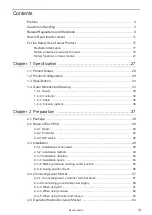
Page 27: ...27 Chapter 1 Specification ME LPM SSM 10...

Page 28: ...iber laser marker w Represents laser output power class as follows 20 Laser output for processing 16W 50 Laser output for processing 40W A0 Laser output for processing 80W e Represents marking field c...

Page 29: ...t included in this product Connect the touch panel console or monitor and mouse to the laser marker to set the marking data and other parameters This display can be used also as a monitor during the o...

Page 30: ...et Laser and general specifications Item Model LP M200 LP M205 LP M500 LP M505 LP MA00 LP MA05 LP MA06 Marking laser Laser type Yb FIBER laser 1064 nm Class 4 laser product Oscillator output 20W 52W 1...

Page 31: ...1 100V AC 390VA 4 3A or less 580VA 6 4A or less 740VA 8 2A or less 200V AC 510VA 2 8A or less 720VA 4 0A or less 830VA 4 6A or less Grounding method Head Controller Direct earth Cooling method Head Na...

Page 32: ...sh drive formatted with FAT32 USB media with security features cannot be used 9 OS versions of which Microsoft has ended support are excluded 10 The power voltage is auto switched 11 The typical value...

Page 33: ...ield X Y LP M200 LP M500 LP MA00 120 mm x 120 mm LP M205 LP M505 LP MA05 220 mm x 220 mm LP MA06 330 mm x 330 mm r Laser pointer emission port 26 mm Aperture diameter 20 mm t Laser emission port 70 mm...

Page 34: ...4x 30 98 50 175 q 27 292 48 Unit mm No Description q Rubber feet installation screw hole four holes on base and both side surfaces M5 depth 6 The rubber feet for controller can be installed on base or...

Page 35: ...ards compatible cable Europe Attached to LP Mxxx LP Mxxx S LP Mxxx LS1 type e Rating 250V CCC standards compatible cable China Attached to LP Mxxx CHN LP Mxxx S CHN type Unit mm Minimum bending radius...

Page 36: ...P40 Unit mm 171 41 5 15 6 55 143 1 2 19 5 2900 70 80 0 8 w e q 60 253 197 128 No Description q Pen holder attaching nut M4 depth 6 both left and right sides w Attaching nut 4 positions M4 depth 6 e Co...

Page 37: ...37 Chapter 2 Preparation ME LPM SSM 10...

Page 38: ...during transportation Both the head and controller are connected with fiber cable and this cable cannot be detached from the device Forcibly detaching them might damage the product Laser marker Head...

Page 39: ...ta are stored into this CD ROM Laser Marker Utility Software for PC setting of laser marker Laser Marker NAVI plus Font Maker Logo Data Conversion Software Export VEC Logo Data Editing Software PDF ma...

Page 40: ...tions on laser marker P 21 4 Laser pointer emission port The emission port of the red laser pointer radiated when using the dual pointer function For details refer to 2 3 6 Lasing position check P 56...

Page 41: ...n LP Mxxx S type Connector for communication between the head and controller for controlling the laser gate which shuts off the laser beam Connect the attached laser gate cable 9 Heat sink This is a f...

Page 42: ...ase of turning ON the power supply after turning OFF leave the interval five seconds or more between ON and OFF Do not turn off the power supply while the system starts during MAIN indicator is flashi...

Page 43: ...nnector for console option 7 USB connector B PC This is the connector for connecting the attached USB cable Connect with PC in using Laser Marker NAVI plus 8 USB connector A USB MEDIA This is the term...

Page 44: ...tached return harness 3 Ethernet port This is the connector for connecting to the external device to control the laser marker with Ethernet For details refer to Serial Communication Guide 4 Return con...

Page 45: ...inal Refer to 3 3 3 Signals on input output terminal P 80 for details 17 Clamp This is the clamp for fixing the AC power cable 18 Cooling fan of the controller Exhaust port This is a cooling fan to re...

Page 46: ...wing operations Laser pumping LSR Shutter control SHT Guide laser GID Laser check radiation SPT Laser power measurement PWM Test marking TST OFF Control by I O for the following operations Laser pumpi...

Page 47: ...e turned on construct a system for re pumping the laser manually as safety protection measures after stop of the laser radiation due to an interlock or other safety functions No 7 No 8 According to th...

Page 48: ...and shocks can be directly transmitted to it Do not install the controller at a place with a lot of oil mist and or dust Take measures to prevent oil contents and dust from entering into the controll...

Page 49: ...tallation plate M6 screw Example of head installation plate Example dimensions of plate for the head are indicated below For plate thickness of 10 mm Unit mm 55 80 93 93 80 80 20 20 55 93 93 40 40 30...

Page 50: ...e compressed air clean the protection glass of the laser emission port regularly Operating with the contaminated laser emission port may lead to deterioration in quality of laser marking or processing...

Page 51: ...ate to the laser marker side The thickness of the installation plate should be 10 mm or more Air nozzle Head installation plate Fixing holes for side Fixing holes for front or rear Install the air noz...

Page 52: ...e 4 mm to 6 mm Tightening torque 2 0 N m or less The rubber feet are attached to the bottom of the controller on shipping Remove the rubber feet in case of fixing the bottom of the controller directly...

Page 53: ...not cross the eye height The laser beam path shall be enclosed with protective enclosure and make sure it is not exposed with direct light or reflected light Do not incorporate the laser marker in a u...

Page 54: ...both the head and controller in a well ventilated place Installing near a heating element could cause the ambient temperature exceeding the specification range which may cause malfunction of the prod...

Page 55: ...em Please contact our sales office for details 103 135 56 B C C A Unit mm Marking center Do not place anything in the area between the laser emission port and lasing object during the marking operatio...

Page 56: ...and marking field can be traced with the red guide laser The marking work position can be adjusted visually by using the guide laser function Y Y X X A B C D Adjust the work distance so that the dot i...

Page 57: ...use a failure A gasket is incorporated in the joint of each cable which keeps the protection structure The performance of the marker head protection structure is ensured only when each cable is proper...

Page 58: ...Unit power cable e Laser gate cable Only for LP Mxxx S type r Output terminal t Input terminal y Interlock connector u Input connector for displacement sensor i Laser gate terminal Only for LP Mxxx S...

Page 59: ...orm the connection of the Power Terminal Block with power off state There is a risk of electrical shock 1 Connect the protective conductor terminal and the frame ground terminal to the grounding part...

Page 60: ...6 Fix the AC power cable with the clamp Screw size M4 Tightening torque 1 0N m Locate the AC power cable beside the fan Locating it in front of the fan may impair the air cooling performance leading...

Page 61: ...as a keyboard 1 OS versions of which Microsoft has ended support are excluded The CPU type memory capacity hard disk space and display function required to operate each OS should be provided in accord...

Page 62: ...n harness to the rear of the controller Do not take out and put in the console in being powered on t q e r w y u No Description q Front side of controller w Rear side of controller e LP ADP40 Optional...

Page 63: ...using monitor and mouse do not connect the return harness USB hub cannot be used for this product There is 1 port on the front of the controller and 2 ports on the back for USB connector A USB mouse c...

Page 64: ...rking start signal from the external devices such as switches or sensors connected to I O terminal Use this operation mode to configure the laser marker without using the external control devices as P...

Page 65: ...ontrols the operation of the laser marker with a key actuated master control Start up 1 Set up the laser marker Connect the head and controller Connect the touch panel console or monitor and mouse to...

Page 66: ...mping by using LASER IN X9 on I O terminal or the serial communication command for the laser pumping LSR 2 If you want to save the file move to FILE screen and click SAVE 3 Turn off the key switch and...

Page 67: ...art marking Turn on power with key switch on controller Edit the file Start test marking Save the file Edit and overwrite the file Start Run operation Marking trigger input Select file to use in Run o...

Page 68: ...the marking start signal from the external devices such as switches or sensors connected to I O terminal 1 Set the marking mode to RUN 2 Turn ON the laser pumping switch on the controller to start la...

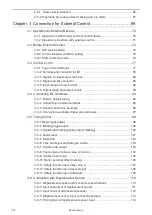
Page 69: ...Chapter 3 Connection for External Control ME LPM SSM 10...

Page 70: ...rminal block I O connector PLC etc External control by serial communication commands RS 232C Ethernet Remote mode operation Controls the laser marker from external devices such as PLC using communicat...

Page 71: ...the ready signal Refer to 3 2 3 Shift to remote mode P 76 Marking Laser radiation Control by serial communication commands I O control Open shutter Select file READY output ON Marking trigger input O...

Page 72: ...unication conditions in the environment setting screen Refer to 3 2 2 Communication condition setting P 75 Refer to 3 2 3 Shift to remote mode P 76 Remote mode ON Communication environment setting Tur...

Page 73: ...DIP switch No 2 select the control method I O or command for some specific operations DIP switch No 2 Control method for specific operations ON Control by serial communication commands for the follow...

Page 74: ...lable CAUTION If the DIP switch No 5 or No 6 are used while turned on construct a system for re pumping the laser manually as safety protection measures after the stop of the laser radiation due to an...

Page 75: ...the counter end output signals in I O connector pin No 32 to 35 respectively 4 To use the serial communication commands set communication conditions for Ethernet or RS 232C For RS 232C Configure the c...

Page 76: ...inal Turn ON the remote mode input X5 of the I O terminal on the rear of the controller X5 REMOTE IN Turn ON the DIP switch No 5 Refer to 3 2 1 DIP switch setting P 73 When DIP switch No 5 is ON the r...

Page 77: ...r I O P 78 w I O connector e Interlock connector 1 Input and output terminals to construct the interlock system to stop the laser radiation Refer to 3 7 Interlock Connector P 115 r Interlock connector...

Page 78: ...utput for the specific functions LP M200 M205 M500 M505 X20 X19 X18 X17 X16 X15 X14 X13 X12 X11 X10 X9 X8 X7 X6 X5 X4 X3 X2 X1 Y14 Y13 Y12 Y11 Y10 Y9 Y8 Y7 Y6 Y5 Y4 Y3 Y2 Y1 Rear of controller I O ter...

Page 79: ...D sub 37 pin female Screw type M2 6 female Hirose Electoric Co Ltd User side D sub 37 pin male Screw type M2 6 male Attached accessories Connector HDCB 37PF 05 Connector Cover HDC CTH 1 10 I O termin...

Page 80: ...ndby output Y5 REMOTE OUT Remote mode output Y6 READY Marking ready output Y7 MARKING Marking output Y8 MARK END Marking end output Y9 LASER OUT Laser pumping completion output Y10 For LP Mxxx Mxxx S...

Page 81: ...X3 0V OUT Internal power power supply for input output 0V Power to operate the laser marker independently Y1 and X3 are the common terminal connected internally Make sure to use X1 or Y3 for the inter...

Page 82: ...r stop 1 input LASER STOP 1A Laser stop 1 input A at LP Mxxx LS1 LASER STOP 1B Laser stop 1 input B Equipped only in LP Mxxx LS1 1 LASER STOP 2A Laser stop 2 input A LASER STOP 2B Laser stop 2 input B...

Page 83: ...ntly X1 and Y3 are the common terminal connected internally Make sure to use X3 or Y1 for the 0V of the internal power 24V X1 and Y3 Do not mix the connecting pattern for using external and internal p...

Page 84: ...put 2 The operation behavior of SHUTTER 2 OUT is the same as Y10 SHUTTER OUT For LP Mxxx S type only L GATE OPREQ Laser gate open request Output turns ON before test marking laser check radiation lase...

Page 85: ...or correction confirm that this output is ON and close the laser gate This is One shot output Time to turn the output ON may be set to any value between 2 to 510 ms by one shot output in the environme...

Page 86: ...CEND 2 6 Counter 1 or 5 end output 35 CEND 3 7 Counter 3 or 7 end output 36 SET OK Setting completion output 37 OUT COM Output common IN COM and OUT COM on the I O connector are connected with IN COM...

Page 87: ...D0 to D15 The input operation is executed at the timing of the edge of set input ON 3 to 18 D0 to D15 Number input Set the number for one of the following targets selected at SELECT 0 to 2 input q Fil...

Page 88: ...down the counter of the counter number 3 by two steps Turn ON D3 which represents the counter number 3 Select 0000 0010 which represents the step times 2 in a 8 bit binary system by specifying ON OFF...

Page 89: ...5 D12 to D15 Rank 3 0 to 15 Rank 8 bit 2 D0 to D7 Rank 0 0 to 255 D8 to D15 Rank 1 0 to 255 External offset Lower 4 bits D0 to D3 External Offset 0 to 15 External offset Lower 8 bits D0 to D7 External...

Page 90: ...input status Radiation details SELECT 0 SELECT 1 SELECT 2 Dual pointer OFF OFF OFF Guide laser Marking character string ON OFF OFF Guide laser Marking field OFF ON OFF Work image ON ON OFF 23 TIME HO...

Page 91: ...t test marking Counting is activated from the initial value again when the counter reaches to the end value The counter end output is available when you set the functional character of the counter in...

Page 92: ...External power 24V DC NPN open collector output PNP open collector output Each input Each input The product can compatible with both NPN transistor output and PNP transistor output However mixing use...

Page 93: ...Each output Output Output The product can compatible with both NPN transistor and PNP transistor However mixing use of NPN PNP is impossible Operate the product NPN transistor output and PNP transist...

Page 94: ...ort circuited Short circuited Short circuited Short circuited Short circuited only for LP Mxxx LS1 I O terminal block 1 X19 is available only with LP Mxxx LS1 models as LASER STOP 1B signal For the ot...

Page 95: ...g patterns If you use the internal power supply of the I O terminal block make sure that the total load does not exceed 300mA If you control the laser marker by the external power such as PLC do not c...

Page 96: ...wer NPN connection 24V OUT IN COM 0V OUT 0V OUT OUT COM TRIG IN VDD OUT 0V Y1 Y2 Y3 Y4 Y5 Y6 Y7 Y8 X1 X2 X3 X4 X5 X6 X7 X8 I O terminal block Sensor PNP connection 24V OUT IN COM 0V OUT TRIG IN VDD OU...

Page 97: ...LASER STOP 2A OUT COM LASER STOP 1B 1 Y8 Y9 Y10 Y11 Y12 Y13 Y14 X8 X9 X10 X11 X12 X13 X14 X15 X16 X17 X18 X19 X20 I O terminal block Laser stop switch etc Laser stop switch etc Laser stop switch door...

Page 98: ...itch STANDBY OUT READY OUT MARKING OUT MARK END OUT REMOTE OUT LASER OUT LASER IN TRIG IN SHUTTER OUT 2 Open Open Open Close Close Close REMOTE IN ALARM OUT Active Low WARNING OUT Active Low SHUTTER B...

Page 99: ...ty of data to be marked When laser pumping is not completed Time for data creation or time for laser pumping whichever is longer T4 10 ms or more Keep the ON status for 10 ms or more T5 2 to 510 ms Th...

Page 100: ...efer to Marking operation timing chart during remote and operating modes P 122 for detail 3 5 3 Equidistant marking flying object marking ON OFF ON OFF ON OFF ON OFF T2 T2 T2 T3 T3 T3 T3 T1 READY OUT...

Page 101: ...entering the SELECT 0 to 2 input as shown in the below table Radiation details SELECT 0 SELECT 1 SELECT 2 Dual pointer OFF OFF OFF Marking contents ON OFF OFF Marking field OFF ON OFF Work image ON ON...

Page 102: ...e T4 When laser pumping is completed Time for data creation It varies depending on the quantity of data to be marked When laser pumping is not completed Time for data creation or time for laser pumpin...

Page 103: ...is set ON the time is held in spite of switching the file No If the TIME HOLD ON OFF is switched in short time each ON OFF hold time should be more than 2 seconds 3 5 7 Counter end output T1 T1 T1 T1...

Page 104: ...r pumping is not completed Time for data creation or time for laser pumping whichever is longer T4 10 ms or more Keep the ON status for 10 ms or more T5 0 5 ms or more After a lapse of 0 5ms or more f...

Page 105: ...value T4 When laser pumping is completed Time for data creation It varies depending on the quantity of data to be marked When laser pumping is not completed Time for data creation or time for laser pu...

Page 106: ...No 21 SELECT 2 No 22 Data No of rank external offset ON OFF OFF 2 Specify the data number of rank external offset function by using D0 to D15 For details see 3 3 4 Signals on I O connector P 86 SET I...

Page 107: ...as Shutter output Item Time Remarks T1 2 to 510 ms Even when the marking is interrupted due to the laser stop input the mark end outputs This signal is a one shot output Set the output time on the en...

Page 108: ...n LP Mxxx Mxxx LS1 type is the same as Shutter output described above Item Time Remarks T1 100 ms or more Keep the ON status for 100 ms or more T2 Time for data creation or time for laser pumping whic...

Page 109: ...r of Shutter 2 output on LP Mxxx Mxxx LS1 type is the same as Shutter output described above Item Time Remarks T1 100 ms or more Keep the ON status for 100 ms or more T2 Time for data creation or time...

Page 110: ...allows that the laser marker outputs the warning of the sensor error when the displacement sensor trigger is input while the shutter is opened When not using the displacement sensor error signal conn...

Page 111: ...ent sensor input Z Z position for laser marker H Displacement value measured by displacement sensor B1 Reference position of laser marker Z 0 mm B2 Reference position of displacement sensor H 0 mm WD...

Page 112: ...er input No 9 IN COM 2 Input common for displacement sensor trigger input Internal circuit NPN sample PNP sample Input Input No 9 IN COM 2 No 9 IN COM 2 External power 24V DC External power 24V DC NPN...

Page 113: ...lacement sensor input connector Laser marker side 0V displacement sensor power For NPN 24V for PNP 0V Analog ground Output 0 Alarm output Analog current output 24V displacement sensor power Displaceme...

Page 114: ...for 51 ms or more If the marking trigger is input before 51 ms it will affect the marking quality T4 Do not input the displacement sensor trigger while the marking output is ON If the sensor trigger i...

Page 115: ...ch or safety PLC INTERLOCK 1 COM and INTERLOCK 2 COM are not connected to the common terminals IN COM OUT COM of I O terminal and I O connector 2 FEEDBACK 1 OUT on Interlock 1 connector FEEDBACK 2 OUT...

Page 116: ...ng coil of the internal relay in the controller Connect INTERLOCK IN No 3 and INTERLOCK COM No 1 with the non voltage contact dry contact such as a relay or a switch Do not connect with the voltage co...

Page 117: ...specifications 1 2 3 4 5 6 7 Laser marker side terminal DFK MC1 5 7 GF 3 81 Manufactured by Phoenix Contact Accessories Laser gate terminal FK MCP1 5 7 STF 3 81 Terminal No Signal Description 1 OUT C...

Page 118: ...IN COM 3 Pin No 6 L GATE OP IN Pin No 7 L GATE CL IN Inside the laser marker Internal circuit NPN connecting sample Input common IN COM 3 External power supply 24V DC Laser gate input Input NPN open c...

Page 119: ...ax 50 mA PNP connecting sample Output common OUT COM 3 External power 30V DC Max Each output Load Output Laser gate terminal output Max 50 mA Do not apply the voltage exceeding the maximum applied vol...

Page 120: ...of the origin point of the laser gate from STAND BY output If the origin point recovery operation is not going to be performed immediately after start up the connection is not necessary 2 This is the...

Page 121: ...rform the laser gate origin point recovery operation After both L GATE CL OUT 1 and L GATE CL OUT 2 turn ON turn both L GATE OP IN and L GATE CL IN inputs OFF within 50 ms The origin point cannot be r...

Page 122: ...OUT 1 L GATE CL IN L GATE CL OUT 2 LASER OUT Item Time Remarks T1 1 ms or more Input one shot signal of 1 ms or more T2 When the laser gate opens if the marking data generation is not complete marking...

Page 123: ...shot output time is set on the environment setting screen T2 400 ms or less Complete the input of L GATE OP IN one shot signal within 400 ms after detecting L GATE OPREQ output T3 1 ms or more T4 600...

Page 124: ...nd with RS 232C connect the RS 232C port on the rear of the controller to the external control device 5 1 9 6 Rear of controller Laser marker controller side RS 232C port male Connector position Conne...

Page 125: ...ser marker Terminal No Terminal No External controller Cross cable Signal Signal The loop back wiring on the external control device side shown in the above figure is just an example The wiring method...

Page 126: ...223 255 255 255 1 Initial value Unspecified 0 0 0 0 Port 5001 to 65534 except 9090 and 9091 Initial value 9094 Start code Setting request Reading request Reading response STX Normal response ACK Abno...

Page 127: ...er one to many through a HUB or a router Use a HUB or a router that supports 1000BASE T 100BASE TX 10BASE T and Category 5e or higher straight cables for connection HUB or router Straight cable Extern...

Page 128: ...Chapter 4 Maintenance ME LPM SSM 10...

Page 129: ...Main cause for degradation Daily maintenance Replacement when degraded or defective q Protection glass of laser emission port Contamination Cleaning Customer replaceable w Laser gate 1 Aging By our s...

Page 130: ...The surface of the laser emission port may become contaminated by the dust and smoke during the laser marking or processing Using laser marker with the contaminated laser emission port may cause the...

Page 131: ...disconnect the AC power cable 2 Clean the laser emission port with an air duster for optics and wipe it lightly with a soft cloth If a contamination is severe use a soft cloth immersed in ethanol to w...

Page 132: ...lass may suddenly fall out Please make sure to be ready to hold it with a soft cloth 4 Replace the protection glass There is no front or back for the protection glass 5 Attach the protection glass fit...

Page 133: ...filters please contact our sales agency Model Remarks LP AFT50x5 Set of 5 pieces for the controller Steps for cleaning Daily maintenance and replacement of air filter 1 Turn OFF the key switch of the...

Page 134: ...nt interval of the fans The fan does not rotate or the rotating speed is low There is contamination on the fan Abnormal noise is generated from the fan Almost 5 years have passed since delivery The re...

Page 135: ...oling system is used in the head thus the cooling effect will significantly drop if dust or oil is adhered to the surface Clean the head surface according to the operation environment Do not clean the...

Page 136: ...tive and unable to irradiate the laser Replacement interval Deterioration in quality of laser marking or processing density reduction incomplete marking or processing is observed Setting a large value...

Page 137: ...Celsius degree The 10 difference might occur under the high low temperature Correcting power under normal temperature is recommended Before using this function confirm the laser emission port is clea...

Page 138: ...rker Detector of the laser power meter Laser beam Marking object Setting distance of detector of the power meter Work distance Base position CAUTION Do not place the power meter detector at the focal...

Page 139: ...er laser check radiation is started input the signal from the external device and open the laser gate Refer to 3 8 Control of Laser Gate P 117 for details 8 Confirm if the measurement results are with...

Page 140: ...n to correct not the maximum laser power W value but the laser power setting value If the value of Power correction Laser power is equal to or larger than 100 the setting will be 100 11 Laser output o...

Page 141: ...five years The replacement interval may differ depending on the usage environment and conditions Replacement method Our service representative handles the maintenance and replacement Contact our sale...

Page 142: ...enance and replacement Contact our sales office 4 2 11 Battery inside the controller A lithium primary battery is contained inside the controller as battery for clock or calendar of the laser marker B...

Page 143: ...lt Laser marker model Type Model LP M500 LP M505 LP MA00 LP MA05 LP MA06 Time Lag Fuse Rating 250V 10A 0215010 made by Littelfuse LP M200 LP M205 Time Lag Fuse Rating 250V 6 3A 021506 3 made by Littel...

Page 144: ...ered in the laser marker periodically in case of replacing laser markers for repairing and maintaining purposes Steps for obtaining backup data Daily maintenance 1 Insert a USB memory to the controlle...

Page 145: ...e serial numbers Check it on laser marker The serial No of the laser marker is written on the area marked by a circle in the figure below Rear of head Rear of controller LP M200 M205 M500 M505 LP MA00...

Page 146: ...electrical and electronic products and batteries must not be mixed with general household waste For proper treatment recovery and recycling of old products and batteries please take them to applicabl...

Page 147: ...od is never described with the replacing method of the battery The customer should call our service representative to replace the battery 1 Remove the top cover of the controller Remove 2 screws of th...

Page 148: ...Troubleshooting ME LPM SSM 10...

Page 149: ...Restore the original condition of the safety equipment connected to the interlock connector Laser stop 2 on input terminal is in OPEN status or safety equipment such as door and switch connected to th...

Page 150: ...ows nothing Monitor is not turned on Check power to monitor Monitor cable is not connected Check that monitor cable is securely connected to connector VGA OUT on back of controller VGA compatible moni...

Page 151: ...Object is not in place Correct position of object Guide indication feature may be helpful for this purpose The laser marker is set for the marking on flying objects despite the static object Set Movi...

Page 152: ...ets write conditions For Trigger Marking Check if one shot signal of 10 ms or longer is provided per marking cycle For Equidistant Marking Check if status of the signal remains on during marking When...

Page 153: ...o that bottom surface of laser marker head and target surface of object are parallel with each other For LP M LP Z series Setting of Uniform Spot Mode is not appropriate Set the Uniform Spot mode with...

Page 154: ...are continuous vibrations coming from surrounding equipment such as motor and press Perform vibration prevention measures There are irregular vibrations coming from surrounding equipment such as air...

Page 155: ...o meandering motion of conveyor Secure objects to prevent misalignment Marking character pitch is unstable The line speed at the marking position is different from the speed at the installation site o...

Page 156: ...nd B phases Number encoder pulses Number of pulses mm x 4 Either A or B phase signal is refused A and B phase used Check that signal is applied to A and B phase terminals of encoder Measured number of...

Page 157: ...een indicates the valid communication port RS 232C is selected at factory shipment The RS 232C cable is connected to the wrong connector RETURN OUT Connect the RS 232C cable to RS 232C connector on th...

Page 158: ...utter command SHT To change the DIP setting the switch of the laser marker should be set at power OFF state LP Mxxx S type Since the returning to the original position of the laser gate is not perform...

Page 159: ...on permission MKM command File Change No Specified FNO File Change Comment Specified FNN Shutter Control SHT Command Reception Permission MKM Laser Control LSR Counter Reset CTR Status Request STS Mar...

Page 160: ...asy to run out Contact our sales office for replacement of internal battery A USB flash drive cannot be recognized A USB flash drive with a security function is used The file system selected when form...

Page 161: ...or description Measures E002 Emergency stop button of controller is pushed Except for LS1 models Release emergency stop button of controller by turning it in arrow direction E004 Laser Stop 2 of the i...

Page 162: ...ke sure cooling fan operates When not recovered contact our sales office E250 3 Detected a decrease in power supply voltage Check and correct the power status Check the noise influence to the AC power...

Page 163: ...tion Check wiring and control procedure for the I O terminal block wiring to communication port and the procedure of the communication command 1 Error that may occur for LP M LP Z series only 2 Error...

Page 164: ...ened The laser gate is not opened when the test marking laser check radiation or laser power measurement is started Input the laser gate control signals for the returning to the original position afte...

Page 165: ...mory Marking data is too large The line length is too long spiral etc Reduce numbers of characters and logo data Reduce numbers of step repeat Reduce numbers of a start point and a end point of charac...

Page 166: ...e entities which are not supported by laser marker in the DXF file Reduce the number of layers to 128 or less E670 1 Existed 3D marking data outside of marking area Adjust the setting of 3D work with...

Page 167: ...700 Unable to lase as laser pumping is turned OFF Turn ON the laser pumping and after the laser pumping has completed start marking E701 Started laser power check in laser pumping OFF state Turn ON th...

Page 168: ...height Correct the Separator Height W or One Bar Code H settings so that the height is larger than the Line Width in the laser settings If you want to remove the separator set 0 to the Separator Heigh...

Page 169: ...Index ME LPM SSM 10...

Page 170: ...Space 54 Interlock Connector 25 115 Interlock System 26 Internal power 95 I O 77 I O Connector 45 78 86 I O terminal block 78 K Key Switch 42 L Labels 23 Laser emission port 130 Laser Gate 22 117 141...

Page 171: ...ctions 21 25 Safety measures 10 Safety Protection Measures 19 Serial No 145 Shutter 22 142 Signal cable 35 Signal Connector 40 44 Standards 9 Start up 65 T Target Laser Marker 12 Termination 66 Test m...

Page 172: ...172 MEMO No 9000 0066 34V ME LPM SSM 10...

Page 173: ...No 9000 0066 34V...

Page 174: ...Industrial Devices SUNX Co Ltd 2013 2021 July 2021 9000 0066 34V Panasonic Industrial Devices SUNX Co Ltd https panasonic net id pidsx global Please visit our website for inquiries and about our sale...

Reviews: