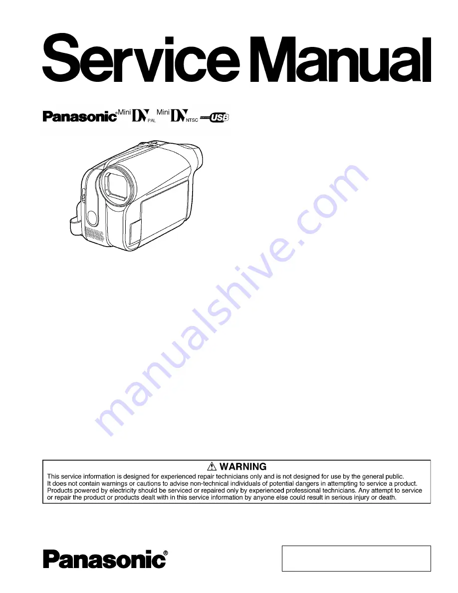
background image

©

2008 Matsushita Electric Industrial Co., Ltd. All

rights

reserved.

Unauthorized

copying

and

distribution is a violation of law.

PV-GS90P

PV-GS90PC
PV-GS90PL
NV-GS90EG
NV-GS90E
NV-GS90EB
NV-GS90EP
NV-GS90EE
NV-GS90EF
NV-GS90EK
NV-GS90GC
NV-GS90GCS
NV-GS90GN
NV-GS98GK

VOL.1

Colour
(S)....................Silver Type

Digital Video Camcorder/Digital Video Camera

ORDER NO.VM0801001CE

B21

Summary of Contents for Palmcorder PV-GS90P

Page 1: ...pying and distribution is a violation of law PV GS90P PV GS90PC PV GS90PL NV GS90EG NV GS90E NV GS90EB NV GS90EP NV GS90EE NV GS90EF NV GS90EK NV GS90GC NV GS90GCS NV GS90GN NV GS98GK VOL 1 Colour S Silver Type Digital Video Camcorder Digital Video Camera ORDER NO VM0801001CE B21 ...

Page 2: ...s Unit 27 9 Measurements and Adjustments 28 9 1 EEPROM Data for spare parts of the MAIN P C B 28 9 2 Service Positions 28 9 3 Location for Connectors of the Main P C B 30 9 4 Electrical Adjustment Procedures 31 9 5 Mechanical Adjustment 35 10 Maintenance 37 10 1 Cleaning Lens Viewfinder and LCD Panel 37 10 2 How to use the DVC Head Cleaning Tape VFK1451 37 11 Schematic Diagrams 39 11 1 OVERALL SCH...

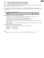
Page 3: ... a shock hazard and the equipment should be repaired and rechecked before it is returned to the customer Figure 1 1 Safety Precaution 1 1 General Guidelines 1 IMPORTANT SAFETY NOTICE There are special components used in this equipment which are important for safety These parts are marked by in the Schematic Diagrams Circuit Board Layout Exploded Views and Replacement Parts List It is essential tha...

Page 4: ...ssembly 3 Use only a grounded tip soldering iron to solder or unsolder ES devices 4 Use only an antistatic solder removal device Some solder removal devices not classified as antistatic ESD protected can generate electrical charge sufficient to damage ES devices 5 Do not use freon propelled chemicals These can generate electrical charges sufficient to damage ES devices 6 Do not remove a replacemen...

Page 5: ...d Free Solder PbF The lead free solder has to be used when repairing the equipment for which the lead free solder is used Definition The letter of PbF is printed on the PCB using the lead free solder To put lead free solder it should be well molten and mixed with the original lead free solder Remove the remaining lead free solder on the PCB cleanly for soldering of the new IC Since the melting poi...

Page 6: ...t not be used until a replacement cover is obtained A replacement fuse cover can be purchased from your local Panasonic Dealer If the fitted moulded plug is unsuitable for the socket outlet in your home then the fuse should be removed and the plug cut off and disposed of safety There is a danger of severe electrical shock if the cut off plug is inserted into any 13 ampere socket If a new plug is t...

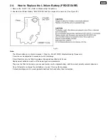
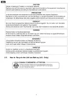
Page 7: ...t must never be subjected to excessive heat or discharge It must therefore only be fitted in equipment designed specifically for its use Replacement batteries must be of the same type and manufacture They must be fitted in the same manner and location as the original battery with the correct polarity contacts observed Do not attempt to re charge the old battery or re use it for any other purpose I...

Page 8: ...2 5 How to Recycle the Lithium Battery U S Only 8 PV GS90P ...

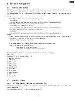
Page 9: ...e used when ordering Notes 2 1 This service manual does not contain the following information because of the impossibility of sevicing at component level 1 Schematic Diagram Block Diagram and P C B layout of Main P C B 2 Parts List for individual parts of Main P C B 2 The following category are recycle module part Please send them to Central Repair Center Main P C B LSEP8439A1 PV GS90P PC PL LSEP8...

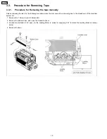
Page 10: ... when the disc cannot be removeing due to the breakdown of the electrical system etc 1 Remove the 1 Screw A and 3 Screws B 2 Remove the Bottom Case and open the Cassette Cover 3 Connect two batteries 1 5V spec to the Loading Motor in series for supplying 3 0V to rotate the Loading Motor as shown below 4 Remove the tape 10 PV GS90P ...

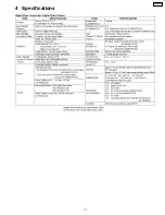
Page 11: ...4 Specifications 11 PV GS90P ...

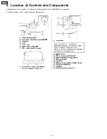
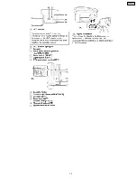
Page 12: ...5 Location of Controls and Components Followings are the Location of Controls and Components for PV GS90P PC as a sample For other models refer to each Operatin Instructions 12 PV GS90P ...

Page 13: ...13 PV GS90P ...

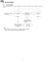
Page 14: ...6 Service Mode 6 1 Error Display PUSH THE RESET SWITCH is displayed automatically on the EVF or the LCD Monitor when an undesirable condition has occured 14 PV GS90P ...

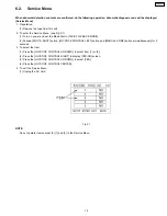
Page 15: ...LAYBACK MODE 2 Pushed PHOTO SHOT button JOYSTICK CONTROL LEFT button and MANUAL AF MF button simmultaneously for 3 seconds 3 To select the Item 1 Press the JOYSTICK CONTROL UP DOWN to select item 1 or 3 2 Press the JOYSTICK CONTROL RIGHT to display YES NO screen 3 Press the JOYSTICK CONTROL UP DOWN to select YES 4 Press the JOYSTICK CONTROL CENTER 4 To exit the Service Menu 1 Unplug the AC Cord Fi...

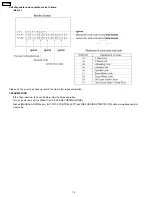
Page 16: ...the clear after repair completion CLEAR METHOD If the Tape inserted take out it before Service Mode operation Turn on power and set the Mode Dial to TAPE RECORDING MODE Pushed MANUAL AF MF button JOYSTICK CONTROL LEFT and RECORDING START STOP button simmultaneously for 3 seconds 16 PV GS90P ...

Page 17: ...7 Service Fixture Tools 7 1 Service Tools and Equipment 17 PV GS90P ...

Page 18: ... 8 1 Disassembly Frow Chart This flow chart indicates the disassembly steps the cabinet parts P C B and Mecha Unit in order to access to be serviced When reinstalling perform the steps in the reverse order 8 2 P C B Layout Fig F1 18 PV GS90P ...

Page 19: ...1 FP91 EVF Battery Case Unit 5 Main P C B Fig D7 2 Screws L 5 Connectors FP21 FP22 FP23 FP24 FP61 Main P C B 6 Mecha Unit Fig D8 Open the Cassette Cover 3 Screws M Mecha Unit 7 Front P C B Fig D9 2 Screws N Front P C B 8 LCD Unit Side R P C B Fig D10 1 Screw O 2 Screws P LCD Unit Fig D11 5 Screws Q Speaker Angle Speaker Side R P C B 9 LCD Backlight P C B Fig D12 2 Screws R 8 Tabs 1 Connector FP810...

Page 20: ...Fig D3 Fig D4 Fig D5 Fig D6 20 PV GS90P ...

Page 21: ...Fig D7 Fig D8 Fig D9 Fig D10 21 PV GS90P ...

Page 22: ...Fig D11 Fig D12 Fig D13 Fig D14 22 PV GS90P ...

Page 23: ...Fig D15 Fig D16 Fig D17 Fig D18 23 PV GS90P ...

Page 24: ...crew Connector Flex Other 1 Cassette Up Unit Fig M1 It makes the mechanism position in Eject condition For Battery Fig M2 Raise the Cassette Up Unit while pushing 2 ridbs Remove the Cassette Up Unit from rail department 2 Cylinder Unit Fig M3 1 Screw A Fig M4 3 Screw B Cylinder Unit Fig M1 24 PV GS90P ...

Page 25: ...Fig M2 Fig M3 25 PV GS90P ...

Page 26: ...Fig M4 26 PV GS90P ...

Page 27: ...e following flowchart describes order or steps for removing the Camera lens unit and certain printed circuit boards in order to make access to the item needing service To reassemble the unit follow the steps in reverse order Fig L1 Fig L2 27 PV GS90P ...

Page 28: ...nsult the Adjustment Manual which is available in Adjustment software The Adjustment software is available at TSN Website therefore access to TSN Website at Support Information from NWBG VDBG PAVC 9 2 Service Positions 9 2 1 List of the extension cables Use the following extension cables when checking or adjusting individual circuit boards except module Parts Main P C B 28 PV GS90P ...

Page 29: ...9 2 2 Checking and repairing individual circuit boards except module parts Main P C B How to use extension cables 29 PV GS90P ...

Page 30: ...9 3 Location for Connectors of the Main P C B 30 PV GS90P ...

Page 31: ...essary 9 4 2 Set up manual for Digital Video Camcorder or Digital Video Camera 1 Installation of USB SERIAL Driver Execute the Setup exe file in Com Mass folder by double clicking to install the USB SERIAL driver 2 Set Up a Remove the tape from this unit b To enter the PC connection COM mode push the PHOTO SHOT button RECORDING START STOP button and MANUAL AF MF simultaneously for 3 seconds withou...

Page 32: ...c Connect the PC and Digital Video Comcorder or Digital Video Camera as shown in Fig E1 and E2 Fig E1 32 PV GS90P ...

Page 33: ... jig mentions it setup electric adjustment Ref Parts Name Parts No Q ty Remarks 1 Personal Computer 1 With Tatsuin Software 2 AC Adaptor 1 The AC Adaptor for Video Camera 3 DC Cable 1 4 USB Cable 1 5 Infinity Lens Fixation Unit 1 6 TATSUJIN PC Adjustment Program 1 33 PV GS90P ...

Page 34: ...alog will appear Click Yes and Save to save the EEPROM data Fig E3 2 6 When EEPROM data has been saved the menu will appear To perform each adjustment display the adjustment menu by selecting from Camera Adjust or VCR Adjust and select each adjustment item Fig E3 3 Note The adjusted data is stored in the EEPROM IC after each adjustment 7 After adjustment to close the software select Exit in the Fi...

Page 35: ...ope to TP3908 Envelope and TP3906 HID on the Main P C B 3 Play back the Color Bar Standard Tape VFM3010EDS or VFM3110EDS Envelope and HID signal will be output 4 Adjust the S1 post by turning the top of post with Post Height Adjustment Fixture VFK1899 so that the left half of envelope signal becomes as flat as possible 5 Adjust the T1 post by turning the top of post with Post Height Adjustment Fix...

Page 36: ...Fig M1 2 36 PV GS90P ...

Page 37: ... use air Blower to blow off the dust When cleaning the LCD Panel dampen the lens cleaning paper with lens cleaner and the gently wipe the their surface Note A lens cleaning paper and lens cleaner are available at local camera shops and market place 10 2 How to use the DVC Head Cleaning Tape VFK1451 Please use the cleaning tape as described below 37 PV GS90P ...

Page 38: ...38 PV GS90P ...

Page 39: ...NS UNIT USB TERMINAL IC6004 RTC POWER CONTROL IC6003 EEPROM POWER SUPPLY CONTROL CIRCUIT HEAD CYLINDER MOTOR CAPSTAN MOTOR LOADING MOTOR IC1001 POWER SUPPLY IC8001 CONTROLLER SIGNAL PROCESSOR DRIVE IC2201 CYL CAP LOADING MOTOR DRIVE IC3201 RIP MODULATION VITERBI EQ MOTOR DRIVE CONTROL LCD BACKLIGHT P C B 0 33 LCD 2 7 WIDE LCD EVF BACKLIGHT P C B IC7801 IC7802 GYRO IC3001 DUO VIDEO I O VCO COMPRESO...

Page 40: ...DIO R JK7101 K2HC104E0017 GND AV VIDEO AUDIO L PLUG_L SIDE L UNIT REAR CASE UNIT CATCHER BATTERY EVF BACKLIGHT P C B SIDE R P C B EVF LCD PANEL EVF SLIDE SWITCH EVF FPC NC FP8902 COM CKV STV ENB CSV VBB DSD DSG CSH VDD VSS STH CKH2 CKH1 B R G DV OUT FP21 TO EVR FP23 FP22 FP24 2 3 4 5 1 CONTROL TG AFE LENS DRIVE POWER MAIN CONNECTION VIDEO2 MAIN JACK LCD EVF DRIVE VIDEO1 AVIO MAIN P C B LOAD MECHA ...

Page 41: ...SURING INSTRUMENT AND ITS MEASURING CONDITION AND PRODUCT ITSELF IMPORTANT SAFETY NOTICE COMPONENTS IDENTIFIED WITH THE MARK HAVE THE SPECIAL CHARACTERISTICS FOR SAFETY WHEN REPLACING ANY OF THESE COMPONENTS USE ONLY THE SAME TYPE AMP AMP 4 1 4 1 1 4 2 9 2 9 1 7 1 2 2 9 1 7 0 0 0 0 0 0 0 GYRO P SENSOR GYRO P SENSOR 1 3 1 3 1 2 2 9 0 0 0 0 4 8 4 8 0 2 4 2 4 2 4 2 4 2 4 2 4 4 9 R FILTER 4 9 4 2 4 9 ...

Page 42: ...ON NOTE CIRCUIT VOLTAGE AND WAVEFORM DESCRIBED HEREIN SHALL BE REGARDED AS REFERENCE INFORMATION WHEN PROBING DEFECT POINT BECAUSE IT MAY DIFFER FROM AN ACTUAL MEASURING VALUE DUE TO DIFFERENCE OF MEASURING INSTRUMENT AND ITS MEASURING CONDITION AND PRODUCT ITSELF LCD BACKLIGHT P C B AMP TO SHAFT FPC FP8101 TO LCD PANEL FP8102 0 0 5 6 0 1 5 1 0 1 1 1 1 1 4 0 3 1 1 1 4 0 3 1 1 1 4 0 3 1 1 1 4 0 3 0...

Page 43: ...DEFECT POINT BECAUSE IT MAY DIFFER FROM AN ACTUAL MEASURING VALUE DUE TO DIFFERENCE OF MEASURING INSTRUMENT AND ITS MEASURING CONDITION AND PRODUCT ITSELF D C 5 4 3 2 1 B A PV GS90 NV GS90 NV GS98 EVF BACKLIGHT SCHEMATIC DIAGRAM TO EVF FPC FP8901 TO LCD PANEL FP8902 11 6 EVF FPC SCHEMATIC DIAGRAM EVF FPC FOR REFERENCE ONLY TO FP8901 TO FP91 TO EVF BACKLIGHT TO MAIN CN VIDEO MAIN SIGNAL PATH EVF SL...

Page 44: ...M TO MAIN CN 11 10 LCD SHAFT FPC SCHEMATIC DIAGRAM LCD SHAFT FPC FOR REFERENCE ONLY TO MAIN CN VIDEO MAIN SIGNAL PATH TO FP81 TO FP8101 LCD REVERS TO LCD BLACKLIGHT C 5 4 3 2 1 B A PV GS90 NV GS90 NV GS98 LCD SHAFT FPC SCHEMATIC DIAGRAM 11 11 SIDE R SCHEMATIC DIAGRAM TO FP62 C B A 5 4 3 2 1 PV GS90 NV GS90 NV GS98 SIDE R UNIT SCHEMATIC DIAGRAM SIDE R P C B AUDIO MAIN SIGNAL PATH NOTE DO NOT USE AN...

Page 45: ...12 Printed Circuit Board 12 1 EVF BACKLIGHT P C B FOIL SIDE LSEP8365A1 1 A B C D E 2 3 4 5 6 7 8 9 PV GS90 NV GS90 NV GS98 EVF BLACKLIGHT P C B COMPONENT SIDE PV GS90P 45 ...

Page 46: ...12 2 FRONT P C B 1 A B C D E 2 3 4 5 6 7 8 9 COMPONENT SIDE FOIL SIDE LSEP8440B1 PV GS90 NV GS90 NV GS98 FRONT P C B PV GS90P 46 ...

Page 47: ...12 3 LCD BACKLIGHT P C B LSEP8433A1 1 A B C D E 2 3 4 5 6 7 8 9 PV GS90 NV GS90 NV GS98 LCD BLACKLIGHT P C B COMPONENT SIDE FOIL SIDE PV GS90P 47 ...

Page 48: ... COMPONENT SIDE FOIL SIDE 1 A B C D E F 2 3 4 LSEP8453A1 PV GS90 NV GS90 NV GS98 SIDE R P C B 12 4 SIDE R P C B PV GS90P 48 ...

Page 49: ...13 Parts and Exploded Views 13 1 Exploded Views 13 1 1 Frame Casing Section 49 PV GS90P ...

Page 50: ...50 PV GS90P ...

Page 51: ...13 1 2 LCD Section 51 PV GS90P ...

Page 52: ...13 1 3 EVF Section 52 PV GS90P ...

Page 53: ...13 1 4 Camera Lens Section 53 PV GS90P ...

Page 54: ...13 1 5 VCR Mechanism Section 54 PV GS90P ...

Page 55: ...13 1 6 Packing Parts Accessories Section 55 PV GS90P ...

Page 56: ...RING 1 PSECI 106 LSGF0551 BATTERY RELEASE HOLDER 1 PSECI 107 LSYY0818 BATTERY TERMINAL FPC U 1 PSECI 108 LSMA1045 STRAP ANGLE R 1 PSECI 109 LSGQ0263 GRIP BELT U 1 PSECI Ref No Part No Part Name Description Pcs Remarks 110 LSKA0035 RUBBER FOOT 1 PSECI B101 XQN16 BJ4FN SCREW 1 B102 XQN16 BJ4FN SCREW 1 B103 XQN16 BJ4FN SCREW 1 B104 XQN16 BJ4FN SCREW 1 B105 XQN16 BJ4FN SCREW 1 B106 XQN16 BJ4FN SCREW 1...

Page 57: ...NISM U 1 PSECI EXCEPT GC 501 LSYK2358 MECHANISM U 1 GC 501 1 VXA8334 CASSETTE UP U 1 501 2 VEG1704 CYLINDER U 1 B501 VHD1674 ROTOR SET SCREW 1 PSECI B502 VHD1861 SCREW 1 Ref No Part No Part Name Description Pcs Remarks B503 VHD1861 SCREW 1 B504 VHD1861 SCREW 1 B505 VHD1754 SCREW 1 B506 VHD1754 SCREW 1 B507 VHD1583 SCREW 1 PSECI 13 2 6 Packing Parts Accessories Section Parts List Ref No Part No Par...

Page 58: ...No Part Name Description Pcs Remarks C7801 F1J1A106A023 C CAPACITOR CH 10V 10U 1 C7802 F1J1A106A023 C CAPACITOR CH 10V 10U 1 C7803 F3F0J226A055 E CAPACITOR CH 6 3V 22U 1 C7804 F3F0J226A055 E CAPACITOR CH 6 3V 22U 1 D4301 B3AFB0000126 LED 1 PSECI D4302 B0BC6R200019 DIODE 1 PSECI D4303 B0BC6R200019 DIODE 1 PSECI D6503 B0ADEJ000038 DIODE 1 PSECI D6504 B3GA00000062 DIODE 1 D7101 D4ED1120A005 VARISTOR ...

Page 59: ...TOR CH 10V 2 2U 1 C8113 F1H1A105A036 C CAPACITOR CH 10V 1U 1 C8116 F1H0J1050012 C CAPACITOR CH 6 3V 1U 1 D8101 MAZ80620ML DIODE 1 Ref No Part No Part Name Description Pcs Remarks D8102 B3AFB0000215 LED 1 PSECI D8104 B3AFB0000215 LED 1 PSECI D8107 B3AFB0000215 LED 1 PSECI D8109 B3AFB0000215 LED 1 PSECI D8113 MAZ80510ML DIODE 1 FP8101 K1MN22BA0197 CONNECTOR 22P 1 FP8102 K1MN24BA0196 CONNECTOR 24P 1 ...

Reviews: