


Reviews:
No comments
Related manuals for RQ-S11

RQ-L31 - Cassette Dictaphone
Brand: Panasonic Pages: 7
WDR-3
Brand: T&D Pages: 4
Perlcorder S950
Brand: Olympus Pages: 28
14-1164
Brand: Optimus Pages: 36
CXR123
Brand: Coby Pages: 48
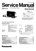
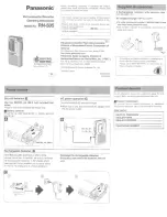
RQ-SX44
Brand: Panasonic Pages: 26
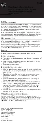
3-5369
Brand: GE Pages: 4
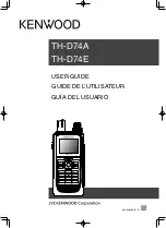
TH-D74A
Brand: Kenwood Pages: 148
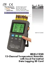
RDXL12SD
Brand: Omega Pages: 20
AK95
Brand: Panasonic Pages: 27
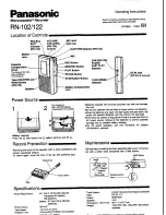
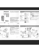
RN-102
Brand: Panasonic Pages: 2
RN-405
Brand: Panasonic Pages: 4
RN-505
Brand: Panasonic Pages: 6

RQ-L319
Brand: Panasonic Pages: 7
RQ-L349
Brand: Panasonic Pages: 7
RQ-L51
Brand: Panasonic Pages: 2
RR830 - Desktop Cassette Transcriber
Brand: Panasonic Pages: 12
transcriber - RR 930 Microcassette
Brand: Panasonic Pages: 12


