background image

Summary of Contents for TH-50PV500E

Page 1: ...is service information is designed for experienced repair technicians only and is not designed for use by the general public It does not contain warnings or cautions to advise non technical individuals of potential dangers in attempting to service a product Products powered by electricity should be serviced or repaired only by experienced professional technicians Any attempt to service or repair t...

Page 2: ... 12 LED 5 times blink TH 37PA50E PE50B P 13 TH 42PA50E PE50B TH 37PV500E B P 14 TH 42PV500E B TH 50PV500E B P 15 LED 6 times blink TH 37PA50E PE50B P 16 TH 42PA50E PE50B TH 37PV500E B TH 42PV500E B TH 50PV500E B P 17 LED 7 times blink TH 37PA50E PE50B P 18 TH 42PA50E PE50B TH 37PV500E B TH 42PV500E B TH 50PV500E B P 19 LED 8 times blink P 20 v 2 f LED 10 times blink TH 37PA50E PE50B P 21 TH 42PA50...

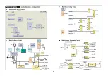
Page 3: ...rcuit P Board Secondary Circuit PA PB Board Regulator Circuit PA BOARD F STB F STB F STB PA10 1 2 3 NR14V IC5602 3 3V 5V Q5606 3 3V Main 3 3V t TunerMAIN ON OFF Sub 3 3V Main 5V Q5603 5V t Tuner_MAIN ON OFF Sub 5V 2 PB BOARD 12Vs W 12Vs W 12Vs S 10Vs W 9Vs w To SS11 To SS12 To PA10 FOR FAN 3 ...

Page 4: ...Power Supply TH 37 42PA50E TH 37PV500E TH 37 42PE50B TH 37PV500B P Board Power Supply Outline P Board Primary Circuit P Board Secondary Circuit PA PB Board Regulator Circuit 4 ...

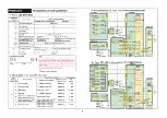
Page 5: ...heck SOS signal that is input to IC9003 in order to know true LED blinking time Check point is the connector s pin or IC9003 s pin as shown in the following table When SOS signal is found please refer to the flow chart of its trouble mode that the SOS signal indicates 2 XV board PE50B PV500B only Check point in the case of 1 time blink LED Check Point location Check output Blinking Trouble Mode co...

Page 6: ...Protection FAN SOS LED 11 times blink PB Board DG Board Sound SOS LED 12 times blink ...

Page 7: ... Power ON shut down occurs immediately So check is necessary before shutdown B Check if power comes up when disconnecting the board which seems to be defective If power comes up when disconnecting a board the board is defective Power comes up means no shutdown 3 Adjustment after P C B exchange When exchange the following boards voltage adjustment is necessary Please refer to Service Manual _ P C B...

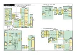
Page 8: ... 5V NG AC Power Code or P Board or other Boards How to find the defective board with GND with GND Yes H Board Yes G Board 8 STB 5V Power Supply 50series STB 5V FUSE 1 4k 10 10 0 MICOM IC9003 D 3 1 1 I DG MICOM IC1104 DG 3 12 DG 2 14 H H H 2 53 27 i H H 2 51 27 33 Check Point Location e g 42PV500E B K Power 2 LED K Power 2 LED ...

Page 9: ...pin Short with GND No Yes Power SW OFF X w OFF Disconnect P5 or PB5 P5 s 6 or 7 or 8 pin Shorr 1 with GND Yes P Board Power SW OFF Disconnect P25 or D25 D25 s 1 or 2 pin Short with GND No PB Board Xyos D Board P Board Power Supply and Protection Circuit r 12V Vsus Vlow stop Relay OFF D3 X DG IC1104 9 LED 3 times blink Trouble Mode and Defective Board Trouble Mode Defective Board 3 3V down SOS D Bo...

Page 10: ...connect SC20 or D20 3 _ After Power SW ON Power comes up Yes C or Panel NG Power SW OFF disconnect P25 or D25 P25 s 7 or 9 pin Short with GND Yves SD Board No SU Board P Board Disconnect SC20 or D20 No Connect D34 Disconnect D33 Cl or After Power SW ON Panel Power comes up Ye C2 or Panel NG Power SW OFF No i Disconnect all flexible cables CB1 CB3 from Cl board Panel 20pin of IC 4 in Cl Short with ...

Page 11: ...flexible cables Connect SU to SC Disconnect SD from SC 2 After Power SW ON Power comes up Yes Spj lG No SD Board SU Board n No i u Power SW OFF No Disconnect P25 or D25 _ D25 s 7 or 9 pin Short with GND VYes Id Board P Boardl Yes C3 or C4 or Panel NG u with Panel from C2 board ex 42PX500 CA5 CA8 After Power SW ON Power comes up VVes In addition Connect D34 p r JDisconnect only D33 I After Power SW...

Page 12: ...After Power SW ON Power comes up TYes ci Board Panel Connect D31 and D32 No In Addition No in Addition No Disconnect D33 and D34 C1 or Disconnect CIO or C20 C2 or Disconnect C21 or C31 C2 or AI1 n r mi P1 AKI After Power SW ON Panel Power comes up sjq Yes C3 o anel NG Disconnect all flexible cables with Panel from C3 board No ex 50PX500 CA8 CA1 1 After Power SW ON Power comes up TYes c3 Boardl Pan...

Page 13: ... Power comes up Yes C2 or Panel NG No C1 or Panel NG Power SW OFF No Disconnect all flexible cables CB1 CB3 from Cl board Panel 20pin of IC 2 in Cl Short with GND Yes Power SW OFF No Disconnect P25 or D25 D25 s 7 or 9 pin Short with GND Ties D Board P Board I Cl Boardl Power SW OFF M No Disconnect all flexible cables CB4 CB7 from C2 board Panel 20pin of IC 2 in C2 Short with GND VYes C2 Board X Co...

Page 14: ...N Power comes u rVes No No Cl or Panel NG Power SW OFF No Disconnect P25 or D25 s D25 s 7 or 9 pin Short with GND Vies Id Boardl p Boardl In addition Disconnect all flexible cables with Panel from Cl board No ies up Panel After Power SW ON Power comes up Yes C2 Board T Panel Cl Board In addition Connect D34 Disconnect only D33 No C4 or Panel NG After Power SW ON 5 Power comes up T Yes C3 or Panel ...

Page 15: ...xible cables with Panel from C2 board No ex 50PX500 CA4 CA7 After Power SW ON Power comes up IYes Disconnect all flexible cables with Panel from C3 board ex 50PX500 CA8 CA11 After Power SW ON Power comes up No Panel C2 Board Panel Cl Board Panel C3 Board Disconnect C41 and C44 20pin of IC 2 in C4 No C5 or C6 or Panel NG Short with GND Disconnect C50 and C51 20pin of IC 2 in C5 Short with GND No C6...

Page 16: ...own Control Pulse NG Disconnect SC20 Power SW ON No Then Power comes up D Boardl Output at D20 s 1 17 18 19 20 pin OK 3 Yes I SC Board Ye Scan es C Board Disconnect SC2 and SS1 1 2 Power SW ON 2 pin VSUS output at P2 s 1 or 2 pin before Shutdown XYes I SS Board P Boardl 1 VSUS about 180V Accurate voltage is described in Panel Label on the chassis 2 CAUTION Before connecting SC2 or SS1 1 after thes...

Page 17: ...G Connect SU to SC Disconnect SD from SC 3 No After Power SW ON Power comes up SU Boardl Xes Yes VSCN or VAD oij SC Control Pulse NG Power SW ON Output at TPVSCN on SC and Output at TPVAD on SC OK before Shutdown 4 P Board Yes SD NG Connect SD to SC Disconnect SU from SC 3 After Power SW ON Ye SC Control Pulse NG Disconnect SC20 n0 Then Power comes up Output at D20 s 1 4 6 pin OK 5 r Yes No SD Boa...

Page 18: ...r SW ON DC15V output at P23 s 1 or 2 pin before Shutdown Yes SU or SD NG Connect SU to SC Disconnect SD from SC 1 No After Power SW ON Power comes up 1 Yes VSCN or VAD orJScan Control Pulse NG No Yes SC Board P Board SU Board Power SW ON Output at TPVSCN on SC and Output at TPVAD on SC OK before Shutdown 2 Yes SD NG Yes SC Board Scan Control Pulse NG SD Board Disconnect SC20 Then Power comes up Ou...

Page 19: ... Board Power SW OFF In addition Disconnect C35 After Power ON Power comes up r YeS r C3 Board SS Disconnect C42 and C43 C42 s 1 or 2 4 or 5 7 or 8 pin Short with GND Yes No Disconnect C52 and C53 No Disconnect C61 No C53 s 3 5 6 pin I C C61 s 3 5 pin Short with GND Short with GND C4 Board r Tves C5 Boardl Yes C6 Board SS Board When Power SW ON No 15V NG DC1 5V output at TP1 5V on SSn before Shutdo...

Page 20: ...sibility SS Energy recovery SS SC D P Board SS SC D P How to find the defective board No VSUS NG Nq Power SW OK Disconnect SS1 1 2 Disconnect SC2 2 3 Connector Model Connector 37 42PA50E PE50B SD SS23 C23 37 42PV500E B HD37 42 SS32 C32 50PV500E B HD50 SS44 C44 4 Output Pin No Output 1 5V DC 5 6 7 8 5V PULSE need oscilloscope ...

Page 21: ...MAIN or SUB Voltage NG Disconnect PA30 or H30 After Power SW ON Power comes up No No PA or DG or XV 1 NG Yes H or TA or Z NG PA50Eb Connect PA30 H30 I ni crtp I Remove XV Board After Power SW ON Power comes up Yes No Remove DG board DG20 s following pins 2 Short with GND Yes DG Board PA Board XV Board No Remove TA board After Power SW ON Power comes up H or Z NG Yes TA Board Disconnect H50 or Z50 ...

Page 22: ...No Connect PA30 H30 PA or DG ori nw i Remove DV Board 1 After Power SW ON Power comes up Tves No PV500B 1 Remove DG board DG20 s following pins 2 Short with GND No Yes DV Board Connect PA30 H30 n0 Remove XV and DV Board After Power SW ON Power comes up Yes XV or DV NG Remove DV Board Install XV Board After Power SW ON Power comes up DG Board PA Board a No DV Boardl XV Board No Remove TA board I IU...

Page 23: ...e Defective Board Sound SOS Z PB H Board How to find the defective board Power OFF 4 7S lor 2 Bln P _7 _ 5or 6_pj n I 1 Short with GND Yes PB orZNG Power OFF Disconnect PA7 or PB7 No PB7 s 1 or 2 pin PB Board JPB7 s 5 or 6 pin Short with GND jfYes n Z Board 500 series only Power Supply and Protection Circuit mi f jlC5803f 10V Vsus Vlow stop 0 0 Relay OFF 0 0 Check Point Location TC su SC SD PB PB7...

Page 24: ...Audio Visual Chain SD DVD DTV Panasonic ideas for life ...

Reviews: