background image

–1–

ACCTB69E   201602-T

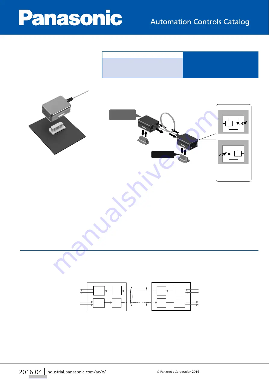
BLOCK DIAGRAM

The differential input signal is converted to an optical signal by the Laser Diode Driver (LDD) and Laser Diode (LD) in the 
plug.
The optical signal is transmitted through the optical fiber and reproduced as differential output signal by the Photo Diode 
(PD) and Trans Impedance Amplifier (TIA).

Vertical insertion type

V

 Series

Active Optical Connector

FEATURES

1. Plug connector is equipped with electrical/optical conversion function 
(bi-direction, Max. 6 Gbps transmission).

2. High speed and wide data rate transmission possible: 20 Mbps to 6 Gbps
3. Integration is possible to a small apparatus with compact, bi-directional 
transmission device.
4. Noise reduction and electrical isolation easily achieved.

APPLICATIONS

Recommended for the following high speed device transmission or electrical 
isolation applications

Electrical signal

(Differential signal)

[Transmitter]

[Receiver]

Optical signal

Receptacle

Plug

(E/O conversion)

Optical fiber

Electrical signal

(Differential signal)

<E/O Converter>

IC

Laser diode

<O/E Converter>

O/E: Optical/Electrical 
        conversion
E/O: Electrical/Optical 
        conversion

IC

Photo diode

• Measuring equipment
• Printer
• Industrial robots, etc.

• Image processing instrument
• Medical equipment

LDD: Laser Diode Driver, LD: Laser Diode, TIA: Trans Impedance Amplifier, PD: Photo Diode

TIA

LD

LDD

LD

TIA

PD

LDD

LD

Differential output

Differential input

Differential input

Differential output

Optical fiber

Downloaded from

Arrow.com.

Summary of Contents for V Series

Page 1: ... compact bi directional transmission device 4 Noise reduction and electrical isolation easily achieved APPLICATIONS Recommended for the following high speed device transmission or electrical isolation applications Electrical signal Differential signal Transmitter Receiver Optical signal Receptacle Plug E O conversion Optical fiber Electrical signal Differential signal E O Converter IC Laser diode ...

Page 2: ...n 1channel Transmission rate 0 02 6 Gbps 8b 10b coding Input output characteristic impedance 80 100 125 Ω Differential input voltage 200 1200 mV Input common mode voltage 150 340 mV Note 1 Input total jitter 0 24 UI Note 2 Input rise time 0 30 UI Input fall time 0 30 UI Differential output voltage 150 220 275 mV Note 2 Output common mode voltage 150 250 275 mV Note 2 Output rise time 0 50 UI Note ...

Page 3: ...7 18 19 20 Optical fiber side 1 2 3 4 5 6 7 8 9 10 Receptacle terminal No Terminal layout diagram Viewed from the top receptacle as transparent Receptacle No Name Wiring 1 Open No connection 2 GND 3 Differential output Differential output 4 Differential output Differential output 5 GND 6 Open No connection 7 Open No connection 8 Power Supply 3 3V DC 9 Power Supply 3 3V DC 10 GND 11 Open No connect...

Page 4: ... m 100 0 AYG4V1A065 L 12 7 9 1 0 60 0 40 5 9 3 9 External dimensions Lot No marking Note 1 Suction face 0 50 0 05 4 50 0 1 8 20 0 50 0 05 3 30 0 10 0 95 0 20 0 03 4 20 5 00 2 80 1 10 1 10 C 0 9 0 1 72 0 20 0 03 General tolerance 0 2 Note 1 The terminal close to the portion to be soldered have nickel barriers except nickel portions Mated height of plug and receptacle 6 5 Downloaded from Arrow com D...

Page 5: ...ordance with JIS C 0806 1990 However not applied to the mounting hole pitch of some connectors Specifications for the plastic reel In accordance with EIAJ ET 7200B 11 5 1 75 4 2 12 0 24 0 0 3 Leading direction after packaging 1 5 dia 0 1 0 25 4 1 Top cover tape Embossed carrier tape Embossed mounting hole Taping reel 380 dia Label Type Direction of tape progress Receptacle Downloaded from Arrow co...

Page 6: ...o the plug impact is applied by dropping or vibration is applied in equipment Sufficient caution should be used with the equipment to avoid such incidents 3 The product cannot be used in a movable parts while the optical fiber is bent Such use may cause deformation of the receptacle or breakage of the optical fiber 4 In order to avoid a load on the plug and receptacle applied by the tensile force ...

Page 7: ...than the ones above please refer to the latest product specifications 8 The temperature profiles given in this catalog are values measured when using the connector on a resin based PC board When performed reflow soldering on a metal board iron aluminum etc or a metal table to mount on a FPC make sure there is no deformation or discoloration of the connector before mounting 9 Consult us when using ...

Page 8: ...ng on the connector type the color of the connector may vary from connector to connector depending on when it is produced Some connectors may change color slightly if subjected to ultraviolet rays during storage This is normal and will not affect the operation of the connector 3 When storing the connectors with the PC boards assembled and components alreeady set be careful not to stack them up so ...

Reviews: