background image

Operating Instructions

Manual de instrucciones

High Defi nition Plasma Display

Pantalla de Plasma de Alta Defi nición

TQB2AA0762

The illustration shown is an image.

Before connecting, operating or adjusting this product, please read these instructions completely. 

Please keep this manual for future reference.

TH-50PF10UK
TH-65PF10UK

Model No.

Número de modelo.

La ilustración mostrada es una imagen.

Antes de conectar, utilizar o ajustar este producto, lea completamente este manual de instrucciones; 

y guárdelo para consultarlo en el futuro en caso de ser necesario.

English

Español

Summary of Contents for Viera TH-50PF10

Page 1: ...ting or adjusting this product please read these instructions completely Please keep this manual for future reference TH 50PF10UK TH 65PF10UK Model No N mero de modelo La ilustraci n mostrada es una i...

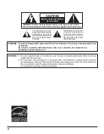
Page 2: ...O NOT OPEN WARNING To prevent damage which may result in fire or shock hazard do not expose this apparatus to rain or moisture Do not place containers with water flower vase cups cosmetics etc above t...

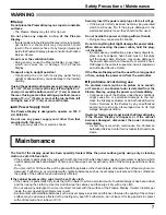
Page 3: ...nt of the obsolete outlet 10 Protect the power cord from being walked on or pinched particularly at plugs convenience receptacles and the point where they exit from the apparatus 11 Only use attachmen...

Page 4: ...ols 21 Adjusting POS SIZE 22 MULTI PIP 24 Advanced PIP 25 PICTURE Adjustments 26 ADVANCED SETTINGS 27 SOUND Adjustment 28 SDI Sound Output 29 SURROUND 29 MUTE 29 Digital Zoom 30 PRESENT TIME SETUP SET...

Page 5: ...ference that may cause undesired operation FCC CAUTION To assure continued compliance use only shielded interface cables when connecting to computer or peripheral devices Any changes or modifications...

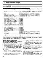
Page 6: ...an extended period as this can cause a permanent image retention to remain on the Plasma Display Examples of still pictures include logos video games computer images teletext and images displayed in...

Page 7: ...right position Transporting the unit with its display panel facing upright or downward may cause damage to the internal circuitry If using the pedestal optional accessory leave a space of 3 15 16 10 c...

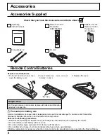
Page 8: ...ix battery types example Zinc Carbon with Alkaline 4 Do not attempt to charge short circuit disassemble heat or burn used batteries 5 Battery replacement is necessary when the remote control acts spor...

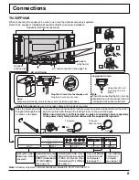
Page 9: ...cially in the power cord firmly bind all cables with the supplied fixing band From SERIAL Terminal on Computer see page 12 From EXTERNAL monitor terminal on Computer see page 11 AC cord connection see...

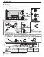
Page 10: ...xing band AC cord connection see page 14 To tighten To loosen Pull Pull Push the catch Note At factory shipment Terminal boards are installed in SLOT 2 and SLOT 3 AC cord fixing 1 Keep the knob presse...

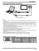
Page 11: ...e is no need to use an adapter for computers with DOS V compatible Mini D sub 15P terminal The computer shown in the illustration is for example purposes only Additional equipment and cables shown are...

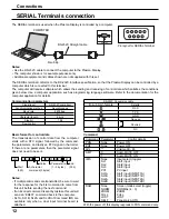
Page 12: ...or the response for the first command to come from this unit before sending the next command If an incorrect command is sent by mistake this unit will send an ER401 command back to the computer SL1A S...

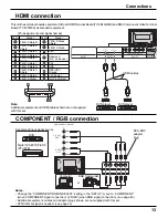
Page 13: ...T2 SLOT3 PR CR R PB CB B Y G AUDIO R L COMPONENT RGB IN HDMI AV OUT HDMI AV OUT HDMI connection This unit has terminal boards equivalent to Dual HDMI Terminal Board TY FB10HMD and BNC Component Video...

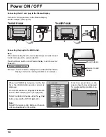
Page 14: ...glish UK Deutsch Fran ais Italiano Espa ol ENGLISH US OSD LANGUAGE SET SELECT PC FULL Connecting the AC cord plug to the Plasma Display Fix the AC cord plug securely to the Plasma Display with the cla...

Page 15: ...the remote control to turn the Plasma Display on Power Indicator Green Turn the power to the Plasma Display off by pressing the switch on the unit when the Plasma Display is on or in standby mode Not...

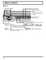
Page 16: ...Indicator not illuminated The unit will still consume some power as long as the power cord is still inserted into the wall outlet Standby Red Power ON Green DPMS Orange With PC input signal and during...

Page 17: ...minutes remain OFF TIMER 3 will flash The off timer is cancelled if a power interruption occurs Status button Press the Status button to display the current system status 1 Input label 2 Aspect mode s...

Page 18: ...MAL OFF ON PICTURE 1 Press to select 2 Press to access each adjust screen To POS SIZE adjust menu see page 22 To SOUND adjust menu see page 28 0 0 0 1 2 SOUND NORMAL NORMALIZE STANDARD OFF TREBLE AUDI...

Page 19: ...UNCTION OFF OFF PRESENT TIME OF DAY 99 99 Press the R button to return to SET UP menu Press to select START TIME FINISH TIME When TIME OF DAY is selected Press to select SHOW DURATION SAVER DURATION W...

Page 20: ...into the SLOT Select to match the signals from the source connected to the component RGB input terminals see page 42 In 2 screen display the same input mode cannot be selected for the main picture and...

Page 21: ...y become enlarged depending on the picture source allowing you to view the picture at its maximum size Notes Panasonic AUTO mode is designed to automatically adjust the aspect ratio to handle a mix of...

Page 22: ...525 480 60i 60p 625 575 50i 50p 1125 1080 60i 50i 60p 50p 24p 25p 30p 24sF 1250 1080 50i 750 720 60p 50p each and RGB PC Digital signals are memorized for each frequency If a Cue or Rew signal from a...

Page 23: ...be adjusted automatically Select NORMALIZE in POS SIZE and press the ACTION button when appropriate adjustment cannot be made H POS Adjust the horizontal position H SIZE Adjust the horizontal size V...

Page 24: ...UT lock in Options menu is set to other than Off MULTI PIP function isn t available Sound output is from the picture which is selected in Audio OUT PIP see page 28 In 2 screen display the same input m...

Page 25: ...e possible to discern details on them satisfactorily Following combinations of two analog signals cannot be displayed simultaneously Component Component Component PC RGB PC RGB Component PC RGB PC RGB...

Page 26: ...el see next page ADVANCED SETTINGS OFF Displays images with settings of the PICTURE menu Press to enter Advanced Settings COLOR MANAGEMENT ON Enables vivid color adjustment automatically While the PIC...

Page 27: ...fect Details BLACK EXTENSION Less More Adjusts the dark shades of the image in gradation INPUT LEVEL Less More Adjustment of parts which are extremely bright and hard to see This cannot be adjusted wh...

Page 28: ...he desired level by listening to the sound 2 Select to adjust each item While the SOUND menu is displayed if either the N button on the remote control is pressed at any time or the ACTION button is pr...

Page 29: ...annel Channel 1 to Channel 16 Selects left audio channel Right Channel Channel 1 to Channel 16 Selects right audio channel Sound Out ON OFF ON Enables audio output OFF Disables audio output Level Mete...

Page 30: ...and Picture operation see page 24 When MULTI DISPLAY SETUP is ON see page 37 When PORTRAIT SETUP is ON see page 40 When SCREENSAVER WHITE BAR SCROLL is running see page 33 While Digital Zoom is in op...

Page 31: ...EENSAVER MULTI DISPLAY SETUP 99 99 MON PRESENT TIME SETUP PRESENT TIME OF DAY MON 99 99 SET PRESENT TIME OF DAY DAY 10 00 TUE PRESENT TIME SETUP PRESENT TIME OF DAY MON 99 99 SET PRESENT TIME OF DAY D...

Page 32: ...TIME POWER OFF TIME by 15 minutes Press to select POWER ON FUNCTION POWER OFF FUNCTION Press to select ON Press twice to exit from SET UP Note Timer function will not work unless PRESENT TIME OF DAY i...

Page 33: ...urned off the SCREENSAVER will be deactivated Press to select the MODE Press to select each mode items OFF INTERVAL Operates when SHOW DURATION and SAVER DURATION are set up and those times arrive TIM...

Page 34: ...3 1 Press to display the SET UP menu SCREENSAVER For preventing image retention SCREENSAVER START FUNCTION MODE WOBBLING PEAK LIMIT FINISH TIME START TIME WHITE BAR SCROLL OFF 6 15 12 30 OFF OFF SIDE...

Page 35: ...ion guide steps 1 and 2 Notes To reduce the occurrence of image retention set the SIDE BAR ADJUST to BRIGHT The side bar may flash alternate black white depending on the picture being shown on the scr...

Page 36: ...he label of the Input signal to be displayed Select the input signal which you would like to change its label before customizing the Input labels see page 17 20 Note While selecting a Input signal thr...

Page 37: ...AY SETUP menu Press to select the MULTI DISPLAY SETUP Press to select ON or OFF How to setup MULTI DISPLAY group of 16 4 4 group of 4 2 2 group of 9 3 3 1 2 3 2 2 SET UP SCREENSAVER MULTI DISPLAY SETU...

Page 38: ...E5 4 4 Press to select HORIZONTAL SCALE Press to select 1 2 3 4 5 Press to select LOCATION Press to select the required arrangement number A1 E5 Refer to the following A1 OFF AI SYNCHRONIZATION LOCATI...

Page 39: ...to On you can use the remote control without identical ID number during option menu display see page 48 The ID remote control cannot be used when ID select is set to anything other than 0 and the remo...

Page 40: ...elect SEAM HIDES VIDEO Press to select OFF ON How to setup PORTRAIT 1 2 3 4 To hide joints between displays Suitable for moving image display To show joints between displays Suitable for still image d...

Page 41: ...T SETUP SEAM HIDES VIDEO OFF 1 OFF AI SYNCHRONIZATION VIEWING AREA LOCATION 16 9 PORTRAIT SETUP 5 VIEWING AREA Set a mode of image division for PORTRAIT function LOCATION Set a location of image to be...

Page 42: ...d Note When ON this setting only affects NTSC input signals Note Selection may not be possible depending on which optional board is installed 1 2 1 2 PC OFF STANDBY SAVE OFF POWER MANAGEMENT OFF AUTO...

Page 43: ...m adjust mode VIDEO NR Automatically reduces unwanted picture noise Block NR Reduces block noise when playing MPEG videos Mosquito NR Reduces mosquito noise around subtitles on MPEG videos Note VIDEO...

Page 44: ...system to match the input signal When selecting AUTO the color system is automatically selected from NTSC PAL SECAM however M NTSC signal is not displayed properly depending on the attached terminal...

Page 45: ...G signal which is input from the G connector VBS Uses a synchronized signal of Composite Sync input which is input from the HD connector Displays the H Horizontal V Vertical frequencies This display i...

Page 46: ...he adjusted signal is displayed see page 20 Signal can be displayed when the Terminal board is installed This menu is available only when INPUT lock is Off When a dual input terminal board is attached...

Page 47: ...anything other than Off is set the value will be fixed as the value input in the single screen display mode When a dual input terminal board is attached A or B is displayed depending on the selected i...

Page 48: ...l image display size on screen On Sets the image display size approximately 95 of the normal image display Off On Notes This setting is valid only when the input signals are as follows NTSC PAL SECAM...

Page 49: ...it is in standby mode and also the power is being supplied to a terminal board the unit will start supplying the power to the board with time delay according to the setting The power indicator lights...

Page 50: ...OM AVL 10 07 08 1 Program Program number Options Adjustments Weekly Command Timer You can set 7 day timer programming by setting time and command Note Before setting Weekly Command Timer set PRESENT T...

Page 51: ...lect Command No Press to select a command number 6 Press to select Time Command Press to set each item Time Set the time to execute a command program Pressing or button once changes Time 1 minute Pres...

Page 52: ...p menu is displayed 2 Press the Volume Up or Down button to select OSD LANGUAGE 3 Press and hold the ENTER button till the SHIPPING menu is displayed 4 Press the Volume Up or Down button to select YES...

Page 53: ...between image and audio depending on the type of input signal However this is not a malfunction Plasma Display panel Symptoms Check The screen darkens slightly when bright pictures with minimal moveme...

Page 54: ...9 55 50 00 29 1 024 768 60 Hz 48 36 60 00 65 0 30 1 024 768 70 Hz 56 48 70 07 75 0 31 1 024 768 75 Hz 60 02 75 03 78 75 32 1 024 768 85 Hz 68 68 85 00 94 5 33 1 066 600 60 Hz 37 64 59 94 53 0 34 1 152...

Page 55: ...5 3 625 50p 50 00 31 25 27 00 720 864 576 625 4 750 60p 60 00 45 00 74 25 1280 1650 720 750 5 750 50p 50 00 37 50 74 25 1280 1980 720 750 6 1125 60i 60 00 33 75 74 25 1920 2200 1080 1125 7 1125 50i 50...

Page 56: ...ture mode Picture in Picture 36 DWA POP Dual Picture mode Picture out Picture 37 DWA SWP Swap main picture and sub picture when PIP mode 38 DWA TWN Dual Picture mode Picture and Picture 39 IMS PC1 Inp...

Page 57: ...0 Hz Connection terminals HDMI A B TYPE A Connector 2 COMPONENT RGB IN Y G BNC PB B BNC PR R BNC AUDIO IN RCA PIN JACK 2 with sync 1 0 Vp p 75 0 7 Vp p 75 0 5 Vrms high impedance PC IN HIGH DENSITY MI...

Page 58: ...R CONSEQUENTIAL DAMAGES INCLUDING WITHOUT LIMITION DAMAGE TO DISCS RESULTING FROM THE USE OF THIS PRODUCT OR ARISING OUT OF ANY BREACH OF THE WARRANTY ALL EXPRESS AND IMPLIED WARRANTIES INCLUDING THE...

Page 59: ...coverage period Proof of product purchase is a condition of warranty service The owner must produce the product purchase receipt or other satisfactory evidence of date of original purchase This warran...

Page 60: ...llas Region 6226 Abington Way Houston TX 77008 713 802 2726 No CA Northwest Region 5870 Stone Ridge 3 Pleasanton CA 925 416 5108 Government Marketing Department 52 West Gude Drive Rockville MD 20850 3...

Reviews: