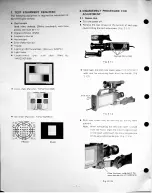
Page 1: ...Beam current readjustment 12 Dynamic focus adjustment 12 Optical black OB correction and OB offset adjustment Input level adjustment 13 Vertical edge balance adjustment 13 Y gain adjustment 13 R and B...
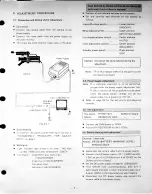
Page 2: ...hree proves one must be 1 1 Digital voltmeter DVM Frequency counter Vectorscope Color video monitor Tripod Lighting 140 footcandles 1 400 lux 3200 K Light meter Logarithmic YWV2310RB99 Slide back the...
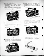
Page 3: ...B viewed from the front Process Circuit Board YWV3110PZK2 Remove the three screws on the bottom and remove the top cover Remove three screws which hold the printed circuit board PCB in order to gain a...
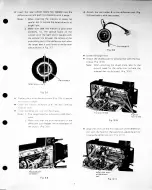
Page 4: ...holder B from the chassis by pulling it back ward Fig 3 5 Loosen the vidicon holding screw and push the vidicon out in the direction of the lens Fig 3 6 Vidicon socket shield case B Disconnect the vid...
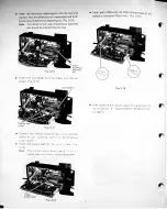
Page 5: ...e deflection coil and the preamplifier circuit board Fig 3 10 Align the ditch on the front portion of the deflection coil with the hole for the back focus adjusting pin by moving the deflection coil F...
Page 6: ...ed after the vidicon rotation adjustment Insert the backfocus adjusting pin into the hole and confirm that the deflection coil moves back and forth by turning the backfocus adjusting pin Fig 3 12 Note...
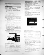
Page 7: ...VM probe to TP104 Adjust 9V ADJ VR104 for 9V 0 02V 0 AC Observe Viewfinder Adjust VR120 BATTERY WARNING LEVEL Deflection Board Lower position INDOOR Upper position WHITE BALANCE Center position AUTO C...
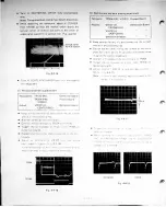
Page 8: ...to TP213 R and TP212 8 Trigger the oscilloscope at H rate Use TP105 on deflection board Turn DYNAMIC FOCUS VR131 VR132 VR133 and VR134 to their mechanical center If a horizontal magenta bar is observ...
Page 9: ...e chart While observing the color monitor adjust FOCUS VR116 for minimum green tint and maximum magenta red throughout picture area If bright green area appears at the corner of the monitor readjust t...
Page 10: ...witch to the ON position lower the liqht ng level so that the lens ns opens fully in order to have minimum nepth of focus Aim the camera at an object fur from the camera Loosen the two backfocus fixin...
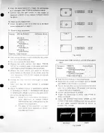
Page 11: ...jumper wire as in the preceding step Aim the camera at the white chart Connect the oscilloscope to TP204 Trigger the oscilloscope at V rate Use TP106 on deflection board Repeat adjusting H SIZE VR105...
Page 12: ...oscope to TP204 and fP105 Trigger the oscilloscope at H rate Use TP105 on deflection board Expand the horizontal blanking period on the oscil loscope Adjust H CENTERING VR107 until the optical bla k w...
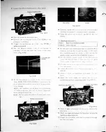
Page 13: ...urning image on the vidicon disappears Connect the oscilloscope to TP203 Trigger the oscilloscope at H rate Use TP105 on deflection board Adjust OB CORRECTION PARA VR226 and OB CORRECTION SAW VR225 so...
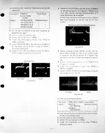
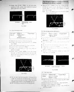
Page 14: ...urth step one step below the crossing step of the gray scale waveform is about 0 4V Fig 4 4 23 Note This is the presetting up for R and B signal tracking 3 adjustment I 0 4V Set the lens iris referrin...
Page 15: ...rlay the B signal and Ysignal on the oscil loscope and adjust Rc Bc GAIN VR216 so that the signal level between the black chip zero step and fifth step crossing step of the gray scale waveform match F...
Page 16: ...oscope to ADD inode and observe the YL R signal thus produced Adjust R H SAWTOOTH VR213 and R H PARA BOLA VR215 to make the waveform as flat as pos sible Fig 4 4 32 Test points TP213 R TP212 B TP214 Y...
Page 17: ...gnal shading adjustment o Cniin t the oscilloscope to TP214 Yj_ chi and TP212 B ch2 Trigger the oscilloscope at H rate Use FP1O5 on deflection board Invert ch2 B TP212 on the oscilloscope Set the osci...
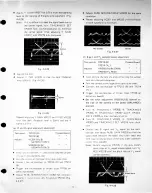
Page 18: ...s the Y j_ signal in the lower half of the gray scale waveform Fig 4 4 41 VR222 R PED VR207 R TRACKING 1 VR205 R TRACKING 2 Test points TP213 R TP214 Y _ VR228 R GAIN Match lower half 7 Match lower ha...
Page 19: ...p at which the B signal no longer tracks with the Y _ signal Fig 4 4 44 In the example shown in Fig 4 4 44 6th step is the point of divergence Turn back TRACKING 3 SET VR219 slowly and stop it at the...
Page 20: ...and TP214 YL Overlay the R signal and the Y _ signal on the oscilloscope and adjust R TRACKING 3 VR203so that the R signal matches the Y _ signal in the 8th 9th step of gray scale waveform Fig 4 4 47...
Page 21: ...r adjust ment are the same as shown in Fig 4 1 1 on page 6 Refer to page 21 for the adjusting controls Aim the camera at the ball chart YWV2100RB03 Adjust H HOLD VR802 to a mid point of horizontal hol...
Page 22: ...80 GROUND Aim the camera at the resolution chart Adjust FOCUS VR804 for best resolution in viewfinder L80 m SIZE VR8C5 V SIZE VR8O2 H HOiO VR801 CONTRAST VR803 BRIGHTNESS Observe Viewfinder ADJUSTING...
Page 23: ...move the circuit board 6 WHITE SET CIRCUIT BOARD REMOVAL White set circuit board i A TP2H W IHd J S f VR223 RrZBc SEPARATION 2 TP212 IBI V A TP2O2 l 3 3VI i i i i i i i i IDAA SHADING O Z VR219 TRACKI...
Page 24: ...ob served Fig 7 9 7 10 Note When installing the control panel to the control panel base set the indoor outdoor switch and the white balance switch on the control panel to the upper posi tion for prop...
Page 25: ...d Fig 8 1 Remove the two screws which hold the handle grip left cover and remove the left cover Fig 8 4 and 5 VCR Start Stop Switch board Disconnect CN208 Remove the two strap Fig 8 3 Disassemble the...