background image


Web Site: www.parallax.com 
Forums: forums.parallax.com 
Sales: sales@parallax.com 
Technical: support@parallax.com 


Office: (916) 624-8333 
Fax: (916) 624-8003 
Sales: (888) 512-1024 
Tech Support: (888) 997-8267 


ELEV-8 Y-6 Multicopter Kit (#80100) Information and Assembly Guide 

Features


Six-rotor system with fixed-pitch blades  


Propeller P8X32A microcontroller flight control board 


Pre-programmed with flight-control software 


Custom plates protect motors and electronics 


Designed to easily attach a camera mount 


Great for FPV (First-Person-View) Camera Systems 


Specifications 


Weight, without battery: 2.7 lbs (1.23 kg) fully assembled  


Payload capacity, excluding battery: ~ 4 lbs (1.8 kg) 


Average assembly time: 8 hours 


Height (assembled): 9 in (23 cm)  


Rotor-to-rotor width (centers): 22 in (55.9 cm) 

Additional Items Required 


RC radio controller and receiver, 5-channel minimum  for flight 


2 LiPo Batteries, 3000 to 4400 mAh 3-cell 30 C discharge rate 


LiPo Battery Charger 


PC running Windows to configure the control board firmware for 

Y6 operation 

Application Ideas 


Hobby RC flying 


Aerial photography 


Flying tele-presence platform 


  CAUTION:  READ ALL WARNINGS AND PRECAUTIONS (PAGE 2) BEFORE ASSEMBLY OR OPERATION!   

Copyright © Parallax Inc. 

ELEV-8 Y-6 Multicopter Kit (#80100) 

Version 1.0    Page 1 of 31  

Summary of Contents for ELEV-8 Y-6

Page 1: ...Camera Systems Specifications Weight without battery 2 7 lbs 1 23 kg fully assembled Payload capacity excluding battery 4 lbs 1 8 kg Average assembly time 8 hours Height assembled 9 in 23 cm Rotor to...

Page 2: ...or others and property damage Perform initial electronic speed controller ESC programming before installing the propeller blades Remove propeller blades before reprogramming the ESCs Establish and tes...

Page 3: ...WG silicone wire stranded blk 710 00042 4 Screw 4 40 1 1 4 PH SS 750 00059 1 25 12 AWG silicone wire stranded red ELEV 8 Y 6 Airframe Kit Contents 80130 710 00006 8 Screw 4 40x1 2 PH SS 800 00021 2 16...

Page 4: ...ell 30 C discharge rate LiPo Battery Charger PC running Windows to configure the control board firmware for Y6 operation Tools Required Soldering iron solder and flux Component vise 1 Phillips screwdr...

Page 5: ...Copyright Parallax Inc ELEV 8 Y 6 Multicopter Kit 80100 Version 1 0 Page 5 of 31...

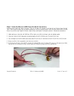
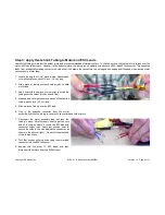
Page 6: ...EC3 connectors wire cutters wire stripper ruler and soldering supplies 2 Using a ruler and wire cutters measure and cut eighteen lengths of the red 16 AWG wire each 14 inches 35 6 cm long 3 Use wire s...

Page 7: ...Solder an opposite gender EC3 connector to the end of each speed controllers blue leads 8 Connect the male EC3 connectors to the female EC3 connectors of your speed controller to verify that they fit...

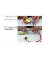
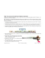
Page 8: ...r blow dryer to shrink the tubing over the solder joint as shown top 4 Measure and cut eighteen more pieces of heat shrink tubing each 1 inch 2 5 cm long 5 Slide a piece of tubing over an ESC lead 6 P...

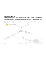
Page 9: ...econd Motor Assembly to the Nylon Standoffs item 8 4 One end of each Boom item 3 has two holes spaced about one inch apart Slide an assembled Motor Mount on this end of each Boom so that the motor lea...

Page 10: ...710 00039 Copyright Parallax Inc ELEV 8 Y 6 Multicopter Kit 80100 Version 1 0 Page 10 of 31...

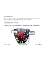
Page 11: ...AWG wire into two pieces approximately 8 inches 20 cm long and then strip 1 4 inch 0 6 cm of insulation from each end You will need three black leads and three red leads for the LED tapes 3 Locate th...

Page 12: ...rt this end into the landing gear mount and be sure that the notch is facing the set screw hole This alignment will allow you to lock the carbon fiber rod in position 2 Apply a light coating of Loctit...

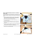
Page 13: ...he Bottom Chassis Plate 2 Locate the correct mounting holes on the Bottom Chassis Plate to use for the rear Motor Boom assembly 3 Position the rear Motor Boom assembly item 2 in the correct place on t...

Page 14: ...Copyright Parallax Inc ELEV 8 Y 6 Multicopter Kit 80100 Version 1 0 Page 14 of 31...

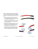
Page 15: ...your LED tape together in the center of your chassis 2 Solder the red leads together in an EC3 connector 3 Solder the black LED tape leads into another EC3 connector 4 Cut two 3 4 inch lengths of the...

Page 16: ...tion off of one end and inch off of the other These two wires will be used for connecting your LEDs to your power harness 3 Solder a female EC3 connector onto the ends of both 3 inch 12 AWG wires with...

Page 17: ...both batteries together using the strap holes indicated and you can trim the leads to about 4 inches If you are going to use a custom layout to accommodate extra electronics or anything else you may...

Page 18: ...to ensure they are properly seated and will not wiggle free 11 Reposition the harness onto the chassis Using a marker or method of your choosing mark the ESCs so you can easily identify which lead go...

Page 19: ...r ESC For the time being the motor to ESC connections do not matter as we will address this issue in a later step Also be sure to connect your LED leads to their power harness leads so that you will h...

Page 20: ...O Plane Mode End point adjustment Set to 50 initially If the ELEV 8 still seems too reactive reduce to 30 until you get used to flying it Dual Rates D R 100 Channel Reverse Normal Hi Tech Spektrum JR...

Page 21: ...port and Batt port at the same time this would damage the card 3 Set the ESC card to the configuration shown in the picture and the table then push OK to program the ESC Repeat with each ESC using the...

Page 22: ...he front of your ELEV 8 Y 6 Multicopter If you have used the checkered stickers and or the LED tapes the front edge would be between the two black checkered white LED Booms 3 Put a piece of tape on th...

Page 23: ...ough the top oval slot as shown in the picture at right 4 Attach the Top Chassis Plate to the standoffs on top of the Booms using six inch Black Pan head Screws 5 For the Control Board Assembly refer...

Page 24: ...Copyright Parallax Inc ELEV 8 Y 6 Multicopter Kit 80100 Version 1 0 Page 24 of 31...

Page 25: ...31500 Copyright Parallax Inc ELEV 8 Y 6 Multicopter Kit 80100 Version 1 0 Page 25 of 31...

Page 26: ...the Hoverfly Firmware Update Client http www hoverflytech com Software_Updates html 2 Once you have the software installed and opened connect your Control Board to your PC Follow the onscreen instruc...

Page 27: ...e 5 8 inch Nylon Standoffs This secures the Control Board Mount Plate to the Top Chassis Plate 4 Align the Control Board Top Plate over the Control Board The small hole near the center of the Top Plat...

Page 28: ...Copyright Parallax Inc ELEV 8 Y 6 Multicopter Kit 80100 Version 1 0 Page 28 of 31...

Page 29: ...eiver Port with the five signal connections listed below Use the 3 wire extension cables included in the ELEV 8 Electronics Kit A Aileron T Throttle R Rudder E Elevator G Gear ON EPA value is Primary...

Page 30: ...the Power Harness 2 Refer to the diagram on this page for the correct placement of each blade 3 Connect each blade to its motor referring to the diagram on the next page The Blade item 2 should be mou...

Page 31: ...Copyright Parallax Inc ELEV 8 Y 6 Multicopter Kit 80100 Version 1 0 Page 31 of 31...

Page 32: ...Mouser Electronics Authorized Distributor Click to View Pricing Inventory Delivery Lifecycle Information Parallax 80100...

Reviews: