background image


1


36% Edge540 ARF 

Instruction Manual 


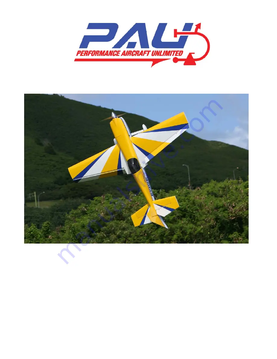
Congratulations and thank you for purchasing the Performance Aircraft Unlimited 36% Edge 540.  The Zivko 
Edge 540 was designed and developed to be the best aerobatic aircraft in the world and it delivered!  Not only 
does this aircraft dominate IAC competition but has also found a home in the Red Bull racing circuit where it 
has won title after title.  The 540 stands for the powerful Lycoming 540 motor, which puts out more than 300hp.  
Made from modern composites, this aircraft is sure to be on the podium for some time to come. 
  
The PAU Edge is no different!  Designed with 2123 sq inches of wing area while keeping the total weight down 
has made this aircraft a true performer.  All wood construction and top quality hardware make it hard to beat.  If 
you want an aircraft precise enough to compete in IMAC or to turn it loose for the wildest 3D maneuvers on the 
planet, the 36% PAU Edge 540 is the only choice.  The Edge 540 return to RC starts today! 


Summary of Contents for 36 Edge540

Page 1: ...he 540 stands for the powerful Lycoming 540 motor which puts out more than 300hp Made from modern composites this aircraft is sure to be on the podium for some time to come The PAU Edge is no different Designed with 2123 sq inches of wing area while keeping the total weight down has made this aircraft a true performer All wood construction and top quality hardware make it hard to beat If you want ...

Page 2: ...ation Chapter 6 Cowling installation Chapter 7 Rudder Installation Chapter 8 Hardware Installation Chapter 9 Radio and Control Surface Setup Chapter 10 Final Inspection and Pre Flight Additional items needed to complete this aircraft which are not included An engine within the recommend range and propeller 8 channel computer radio and receiver recommended Batteries and switches with regulators if ...

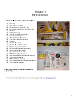
Page 3: ... assembly 1 Canopy 1 Carbon fiber wing 1 Carbon fiber stabilizer tube 4 Nylon wing retention bolts 6 H9 titanium pushrods turnbuckles 1 set of Dubro wheel collars 1 pair of Dubro wheel axels 1 HD Dubro pull pull system 1 Set of aluminum control horn assemblies 1 32oz Dubro fuel tank 8 HD 4 40 Dubro ball links 1 Set of additional various marked hardware 1 Vinyl graphics package If any of these part...

Page 4: ...nsure a scratch free finish Place an to ensure task completion Go over you model as necessary with a covering iron to insure all joints seams and corners are sealed properly Use your iron to ensure the areas where cutouts are needed for your hardware are located and sealed down such as servos tubes and control horn mounting locations Next we ll need to cut out the covering at the locations for har...

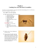
Page 5: ...ware pack marked wheels 9 Fuselage 9 Rudder 9 Tail wheel assembly Not Provided 9 and a 9 16 inch wrench 9 Blue loc tite 9 Allen wrench for wheel collars 9 White wood glue such as Elmer s or Epoxy Fasten the axles to the main landing gear with the lock nuts Using your four wheel collars and wheels center you wheels on the axles Place the collars as close to the wheels as possible but ensure the whe...

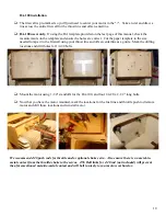
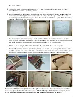
Page 6: ...the mains are on find the pre drilled hole for the tail wheel assembly Insert the tail wheel assembly and lightly tap in flush with a small hammer Next mark the hold down locations drill and mount them with the four wood screws securing the tail wheel assembly Remove the wood screws and coat the holes with thin CA let dry reinstall Install the steel tiller horn just behind the hinge line on the bo...

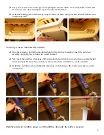
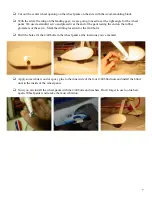
Page 7: ...ing the end on the rubber grommets of the servo Mark the drilling location for the 4 40 bolts Drill the holes for the 4 40 bolts in the wheel pants at the locations you ve marked Apply some white wood or epoxy glue to the inner side of the four 4 40 blind nuts and install the blind nuts to the inside of the wheel pants Now you can install the wheel pants with the 4 40 bolts and washers Don t forge...

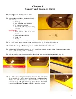
Page 8: ... fit the canopy to the fuselage access hatch to determine screw locations Mark four evenly spaced locations for the screws on each side Double check to ensure all the marked screw locations will go into the hatch rail Remove canopy from the access hatch and drill the marked locations for the canopy screws Install the canopy using the small wood screws If satisfied with the fit remove the canopy an...

Page 9: ...e will cover the installation of two popular engine choices in this manual the DA 85 and the DA 100 motors Follow your engine manufactures instructions for any additional guidance Let s get started Place an to ensure task completion What you will need in this chapter A DA 100 mounting template found in the back of this manual or a DA 85 mounting template found in the back of the DA 85 manual Not P...

Page 10: ...line and offset centerline as a guide Mark the drilling locations and drill holes for 1 4 20 bolts Mount the motor using 1 1 4 standoffs for the DA 100 and four 1 4 20 x 2 1 2 long bolts Now that you have the motor mounted mark the locations for the fuel line and throttle push rod remove motor and drill those locations and reinstall motor We recommend 4 40 push rods for throttle and or optional ch...

Page 11: ...the template provided by DA and made several light plywood rings stacked to achieve the correct standoff which is approximately 1 7 8 off the firewall Mount the motor using 1 7 8 solid mount for the 85 and four 1 4 20 x 3 1 4 long bolts Now that the motor is mounted mark the locations for the fuel line and throttle push rod remove motor and drill those locations and reinstall motor Another recomme...

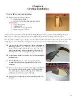
Page 12: ...Since the cowl is preset and uses a ring to mount there will not be much to do here First cut out the bottom opening for cooling For the DA 100 using canisters you will only need to open the bottom of the cowl to exit the air from the cowl If you re using stock exhaust stacks it maybe necessary to cut away the bottom portion of the cowl ring for it to pass the exhaust If using stock mufflers for t...

Page 13: ...control surface into the stabilizer and butt the two surfaces together Move the surface back and forth a couple of times to make sure all the hinges are aligned correctly and the desired throw is attained You will want at least 45 degrees Use some masking tape to hold the surfaces together and let cure for at least eight hours Install the tiller springs you set aside in chapter 2 to the tiller hor...

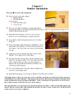
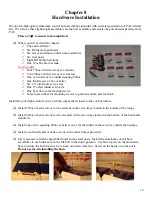
Page 14: ...arm 9 One Fuel dot or other fueling device 9 Some foam rubber for mounting receiver ignition module and fuel tank Install all your flight control servos with the output shaft closest to the control surface Install 150oz or better servos for the ailerons in the servo trays located in the bottom of the wings Install 200oz or better servos for the elevators in the servo trays located in the bottom of...

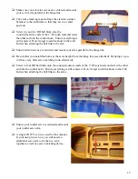
Page 15: ...ered and mount your arms parallel to the hinge line Be sure that you install the horns at the same height from the hinge line see attached By doing so you will have very little servo matching to do afterwards Screw in four HD ball links onto the counterclockwise ends of the 3 H9 push rods and screw the other end into the control horn Ensure everything is still centered Don t forget to add locknuts...

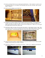
Page 16: ...at connects to your fuel dot or fueling device Make sure you use Tygon fuel tubing inside the tank for the clunk as well Install the fuel tank just in front of the wing tube using zip ties or hook and latch Velcro straps Place a loop in the vent line over the top of the tank to prevent fuel loss during flight and improve flight times Take small zip ties or fuel line clamps and fasten to all the po...

Page 17: ...ide in each half and secure them with the four 4 40 retention bolts Lets install the wings at this time and check our center of gravity CG Install the carbon fiber wing tube Slide in each wing panel and secure them with the four nylon wing retention bolts Tip 8 If the wing is tight you can coat the tube with a little baby powder to aid the insertion of the wing panels Tip 9 For added protection in...

Page 18: ... The recommended low rates for this aircraft are 25 degrees for ailerons with 0 to 20 expo 15 degrees for elevators with 0 to 20 expo 30 degrees for rudder with 0 to 20 expo The recommended high rates for this aircraft are 35 degrees for ailerons with 40 to 70 expo 45 degrees for elevators with 40 to 70 expo 45 degrees for rudder with 30 to 70 expo or as much as you can stand for hardcore flyers C...

Page 19: ... surface hardware Gently tug on each surface to make sure the hinges are properly bonded Check the four 4 40 horizontal stabilizer fasteners and ensure they re in place and secured Check all servos for mounting screws Check servo arm mounting screws and inspect that the 4 40 links have been secured with lock nuts Fill fuel tank and inspect for any leaks Check your batteries in both your aircraft a...

Page 20: ... pointed down whether at vertical or 45 degrees down line Planes must be inspected frequently looking for any loosening screws bolts and glue joints Servos and linkages must be free of play or slop as this is a major cause of flutter and crashes Understanding and applying these few safety and maintenance guidelines will help you get many enjoyable and rewarding flights with your Giant Scale Plane ...

Page 21: ...21 DA 100 Template If printing from Adobe turn off page scaling ...

Page 22: ...22 Throw Template If printing from Adobe turn off page scaling Cut out around all the dotted lines ...

Page 23: ...Wheel Collar Wheel Collar STEP 1 Install wheel pants with typical installation Wheel Wheel Pant Landing Gear Axle ...

Page 24: ...e size of the axle in the center Note 1 4 Thickness usually works but needs to be thicker thank the gap between the end of the axle and the exterior wall of the wheel pant Remove the wheel and re install the wheel pants with the small wood block inserted loosely on the axle Wheel Pant Landing Gear Axle ...

Page 25: ...g epoxy making sure the wheel pants screws are tight the wheel pants are seated in their natural position with no stress on the fiberglass If using a soft wood it is helpful to harden the wood at the hole for the axle with thin CA Wheel Pant Landing Gear Axle ...

Page 26: ...Wood Block Wheel Collar Wheel Collar STEP 4 Re install all components to complete assembly Wheel Wheel Pant Landing Gear Axle ...

Page 27: ...85mm 40mm ENGINE BOX FIREWALL C L 170mm 250mm 330mm 80mm 90mm 36 EDGE DA 100 Canister Set Up 33 00mm 60mm KS 86 Canister ...

Reviews: