background image

Summary of Contents for PG8JAA Series G

Page 1: ...V Wiring 24 Accessories 24 General Venting Requirements 24 Masonry Chimney Requirements 25 Appliance Application Requirements 27 Sidewall Venting 27 START UP ADJUSTMENT AND SAFETY CHECK 32 General 32 Start Up Procedures 32 Adjustments 37 Check Safety Controls 37 Checklist 38 SERVICE AND MAINTENANCE PROCEDURES 43 Introduction 43 Care and Maintenance 44 Sequence of Operation 47 Wiring Diagrams 48 Tr...

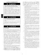
Page 2: ...ns which will result in enhanced installation reliability or operation 1 Use only with type of gas approved for this furnace Refer to the furnace rating plate 2 Install this furnace only in a location and position as spe cified in the Location section of these instructions 3 Provide adequate combustion and ventilation air to the furnace space as specified in Air for Combustion and Ventilation sect...

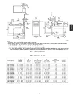
Page 3: ... INLET WIDTH SIZE LB KG LOCATION 14 3 16 360 12 9 16 319 9 5 16 237 12 11 16 322 4 102 104 47 14 3 16 360 12 9 16 319 9 5 16 237 12 11 16 322 4 102 107 49 14 3 16 360 12 9 16 319 9 5 16 237 12 11 16 322 4 102 111 50 14 3 16 360 12 9 16 319 9 5 16 237 12 11 16 322 4 102 115 52 17 1 2 445 15 7 8 403 11 9 16 294 16 406 4 102 126 57 17 1 2 445 15 7 8 403 11 9 16 294 16 406 4 102 127 58 21 533 19 3 8 4...

Page 4: ... 1 po MINIMUM INCHES CLEARANCE TO COMBUSTIBLE CONSTRUCTION DOWNFLOWPOSiTiONS Installation on non combustible floors only For Installation on combustible flooring only when installed on special base Part No KGASB0201ALL or NAHA01101SB Coil Assembly Part No CAR CAP CNPV CNRV END4X ENW4X WENC WTNC WENW OR WTNW 18 inches front clearance required for alcove 1 O Indicates supply or return sides when fur...

Page 5: ...ed metal surface of the fur nace chassis which is close to the control Tools held in a person s hand during grounding will be satisfactorily dis charged 3 After touching the chassis you may proceed to service the control or connecting wires as long as you do nothing to recharge your body with static electricity for example DO NOT move or shuffle your feet do not touch un grounded objects etc 4 If ...

Page 6: ...nd outdoor air may be required for combustion Permanent wave solutions Chlorinated waxes and cleaners Chlorine based swimming pool chemicals Water softening chemicals De icing salts or chemicals Carbon tetrachloride Halogen type refrigerants Cleaning solvents such as perchloroethylene Printing inks paint removers varnishes etc Hydrochloric acid Cements and glues Antistatic fabric softeners for clo...

Page 7: ...ry to remove drywall dust and construction debris from all HVAC system components after construction is completed Verify proper furnace operating conditions including ignition gas input rate air temperature rise and venting according to these installation instructions FIRE HAZARD Failure to follow this warning could result in personal iniury death and or property damage Do not install the furnace ...

Page 8: ... combined input of all gas appliances in the space per Table 2 and b Not less than the sum of the areas of all vent connect ors in the space The opening shall commence within 12 in 300 ram of the ceiling Appliances in the space shall have clearances of at least 1 in 25 ram from the sides and back and 6 in 150 ram from the front The opening shall directly communicate with the outdoors or shall conm...

Page 9: ...00 16 500 19 800 23 1 O0 0 10 178 3 237 8 297 3 186 8 280 3 373 7 467 2 560 6 654 1 0 00 NP NP NP NP NP NP NP NP NP NP Not Permitted TO OUTDOORS 305mm 12 MAX I _J lSQiN _11 1 PER2000 IIB BTU i DUCTS OUTiOORS _ PER 2000 _ I IAI BTUH T 305mm 12 MAX i I CIRCULATING AIR DUCTS 1SQ IN PER 4000 CIRCULATING AIR BTUH _DUCTS 1 I I I I I 12_ 305mm SO IN PER 4000 3TUH cO n O o a F o SQ IN PER 4000 BTUH 12 305...

Page 10: ...pace may be considered a space that freely conmmnicates with the outdoors provided there are adequate permanent ventilation openings directly to out doors having free area of at least 1 in 2 4 000 Btuh of total input rating for all gas appliances in the space 3 In spaces that use the Indoor Combustion Air Method in filtration should be adequate to provide air for combus tion permanent ventilation ...

Page 11: ...hten inside nut to secure arrangement 5 Reinstall bottom closure panel if removed DOWNFLOW INSTALLATION NOTE For downflow applications this furnace is approved for use on combustible flooring when any one of the following 3 accessories are used Special Base KGASB Cased Coil Assembly Part No CNPV CNRV CAR or CAP Coil Box Part No KCAKC 1 Determine application being installed from Table 4 2 Construct...

Page 12: ...re met See Fig 2 and 170 For furnaces with 1 in 25 ram clearance requirement on side set furnace on non combustible blocks bricks or angle iron For crawl space installations if the furnace is not suspended from the floor joists the ground underneath furnace must be level and the furnace set on blocks or bricks Roll Out Protection Provide a minimum 17 3 4 in x 22 in 451 x 559 ram piece of sheet met...

Page 13: ... 483 597 508 AIR DUCTS General Requirements The duct system should be designed and sized according to accepted national standards such as those published by Air Conditioning Contractors Association ACCA Sheet Metal and Air Conditioning Contractors National Association SMACNA or American Society of Heating Refrigerating and Air Conditioning Engineers ASHRAE or consult The Air Systems Design Guideli...

Page 14: ... 1785 1675 1565 1420 1260 Med Low 2020 1955 1880 1805 1730 1630 1535 1420 1275 1135 090 20 Both Sides or 1 High 2530 2450 2365 2270 2165 2065 1940 1805 1670 1505 060090 Side Bottom Med High 2285 2215 2150 2075 1985 1890 1780 1660 1525 1360 Med Low 1995 1945 1900 1840 1770 1685 1600 1480 1350 1180 High 2475 2395 2300 2200 2090 1985 1865 1730 1585 1425 1Side Only Med High 2260 2190 2110 2035 1940 18...

Page 15: ...880 1850 1820 1780 1715 1635 1540 1415 1290 1160 High 2465 2430 2375 2305 2230 2110 2000 1865 1725 1545 155 2o 060155 Bottom Only Both SidesOr I Side Bottom ISide Only Med High Med Low High Med High Med Low High Med High Med Low 2115 2105 2075 2030 1980 1910 1830 1725 1590 1425 U 1800 1790 1770 1735 1695 1640 1570 1465 1345 1225 2375 2285 2200 2105 1995 1870 1730 1570 2155 2135 2095 2040 1975 1895...

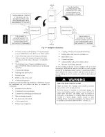
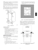
Page 16: ... PER ROD OUTER DGOR ASSEMB_ Fig 15 Horizontal Unit Suspension 22 GAUGE GALVANIZED STRAPS TYPICAL FOR 4 STRAPS METHOD 2 USE 4 8 x 3 4 19 ram SHEET METAL SCREWS FOR EACH STRAR THE STRAPS SHOULD BE VERTICAL AGAINST THE FURNACE SIDES AND NOT PULL AWAY FROM THE FURNACE SIDES BACK OF FURNACE METHOD 1 FOLD ALL STRAPS UNDER FURNACE AND SECURE WTH 4 8 x 3 4 t9 ram SHEET METAL SCREWS 2 SCREWS IN SIDE AND 2 ...

Page 17: ...ACE OF DOOR 30 IN 762mm MIN WORK AREA WHEN USED WITH SINGLE WALL VENT CONNECTIONS H Fig 17 Typical Attic Installation A10164 RETURN AIR SUPPLY T _ AIR UPFLOW RETURN AIR CONFIGURATIONS AND RESTRICTIONS AIR FLOW MODELS RETURN AIR RETURN AiR RETURN AIR RETURN AIR CONNECTION 1 CONNECTmON 2 CONNECTION 3 COMBINATIONS ONLY ONLY ONLY OF 1 2 AND 3 066 060 22 AND YES YES YES YES 20 MODELS ALL OTHER MODELS Y...

Page 18: ...d Horizontal Furnaces Connect supply air duct to flanges on furnace supply air outlet Bend flange upward to 90 with wide duct pliers See Fig 14 The supply air duct must be connected to ONLY the furnace supply outlet air duct flanges or air conditioning coil casing when used DO NOT cut main furnace casing side to attach supply air duct humidifier or other accessories All accessories MUST be connect...

Page 19: ...meter Support all gas piping with appropriate straps hangers etc Use a minimum of I hanger every 6 ft 1 8 M Joint compound pipe dope should be applied sparingly and only to male threads of joints Pipe dope must be resistant to the action of propane gas Table 6 Maximum Capacity of Pipe NOMINAL IRON PIPE SIZE IN MM 1 2 12 7 3 4 19 0 1 25 4 1 1 4 31 8 1 1 2 38 1 INTERNAL LENGTH OF PIPE FT M DIA 10 20...

Page 20: ...han 0 5 psig 14 In W C turn off electric shutoff switch located on furnace gas control valve and accessible manual equipment shutoff valve before and during supply pipe pressure test After all connections have been made purge lines and check for leakage at furnace prior to operating furnace The gas supply pressure shall be within the maximum and minimum inlet supply pressures marked on the rating ...

Page 21: ... NOT remove green ground screw inside J Box The ground screw is not threaded into the casing flange and can be lifted out of the clearance hole in casing while swinging the front edge of the J Box outboard of the casing 2 Cut wire tie on loop in furnace wires attached to J box 3 Move J Box to desired location 4 Fasten J Box to casing with two screws removed in Step 1 5 Route J Box wires within fur...

Page 22: ...r etc full load amps 1 Time delay type is recommended Length shown is as measured 1 way along wire path between unit and service panel for maximum 2 percent voltage drop 12 Complete electrical box wiring and installation Connect line voltage leads as shown in Fig 26 Use best practices NEC for wire bushings strain relief etc 13 Reinstall cover to J Box Do not pinch wires between cover and bracket P...

Page 23: ...WER DOOR SWITCH _ _ _l____ J I I I I I I C e a O l N l i T i R I 115 V FIELD AUXILIARY O SUPPLIED J BOX L DISCONNECT 24 V TERMINAL BLOCK FURNACE I I I I I fT I NOTE 1 I NOTES 1 2 3 THERMOSTAT TERMINALS i i iiiiiiii iiii iiiiii ii_ _iiiiiii i i_iii_ ii _ _iiiiiii iiiii iiiiiiii_ ii_ H 4_ qHF4m _ ttl FIELD SUPPLIED DISCONNECT CONDENSING UNIT TWO WIRE 208 230 OR 460 V THREE PHASE 208 230 V SINGLE PHA...

Page 24: ...w the steps outlined below for each appliance connected to the venting system being placed into operation could result in carbon monoxide poisoning or death The following steps shall be followed for each appliance connected to the venting system being placed into operation while all other appliances connected to the venting system are not in operation 1 Seal any unused openings in venting system 2...

Page 25: ...to be vented into a clay tile lined masonry chimney that is exposed to the outdoors below the roof line provided 1 Vent connector is Type B double wall and 2 This furnace is common vented with at least 1 draft hood equipped appliance and 3 The combined appliance input rating is less than the max imum capacity given in Table 8 and 4 The input rating of each space heating appliance is greater than t...

Page 26: ...r liner _ Remove mortar 1 and tile debris l Clay tile misalignment missing sections gaps No at bottom No Chimney exposed to outdoors below roof line No Chimney is acceptable for use Yes I_ Suitable _ _ J L _ _ Line chimney with property Suitable _ _perly _ lSuitabl e sized listed flexible metal _ _ _t_u H_ U jyes I liner or Type B vent per _ype _ venr tj _ NFGC Vent Sizing Tables and liner or InS ...

Page 27: ...A 5 in 127 mm or 6 in 152 mm vent connector may be required for some model furnaces A field supplied 4 in 102 mm to 5 in 127 mm or 4 in 102 mm to 6 in 152 mm sheet metal increaser fitting is required when 5 in 127 mm or 6 in 152 mm vent connector is used See Fig 28 40 Venting Orientation for approved vent configurations NOTE Vent connector length for connector sizing starts at furnace vent elbow T...

Page 28: ...re 17 to 25 degrees F 5 0 55 99 141 8 52 74 111 154 10 NR 90 125 169 15 NR NR 167 212 20 NR NR 212 258 30 NR NR NR 352 Local 99 Winter Design Temperature 5 to 16 degrees F 6 NR 78 121 166 8 NR 94 135 182 10 NR 111 149 198 15 NR NR 193 247 20 NR NR NR 293 30 NR NR NR 377 Local 99 Winter Design Temperature 10 to 4 degrees F 6 NR NR 145 196 8 NR NR 159 213 10 NR NR 175 231 15 NR NR NR 283 20 NR NR NR...

Page 29: ...Fig 36 132 000 5 127 7 65 Horizontal Left Vent elbow right Fig 37 154 000 5 127 7 65 Vent elbow up then 110 000 Downfiow left Fig 30 036 12 only 5 127 10 3 0 Vent elbow up then 110 000 Downfiow right Fig 33 036 12 only 5 127 10 3 0 4 in 102 mm inside casino or vent guard Including 4 in 102 mm vent section s NOTE All vent configurations must also meet National Fuel Gas Code NFGC venting requirement...

Page 30: ...207 Fig 32 Downflow Application Vent Elbow Left then Up SEE NOTES 1 2 4 5 7 8 9 on the page following these figures Fig 31 Downflow Application Vent Elbow Up A03211 SEE NOTES 1 2 3 4 5 7 8 9 on the page following these figures A03212 Fig 33 Downflow Application Vent Elbow Up then Right SEE NOTES 1 2 4 7 8 9 on the page following these figures Fig 34 Horizontal Left Application Vent Elbow Left A032...

Page 31: ...n field approved Downflow Vent Guard Kit is used in the downflow position See Table 17 for accessory list 4 Type B vent where required refer to the Note 1 above 5 A 4 in 102 mm single wall 26 ga minimum vent must be used inside furnace casing and when the field approved Downflow Vent Guard Kit is used external to the furnace See Table 17 for accessory list 6 Accessory Downflow Vent Guard Kit requi...

Page 32: ... on control until LED goes out approximately 2 sec Gas valve and humidifier will not be turned on See Fig 25 NOTE The furnace control allows all components except the gas valve to be run for short period of time This feature helps diagnose a system problem in case of a component failure Component test feature will not operate if any thermostat signal is present at the control Component test sequen...

Page 33: ...tch f Set thermostat to call for heat g Jumper R and W thermostat connections on furnace control board to start furnace h Remove regulator seal cap and turn regulator adjusting screw counterclockwise out to decrease input rate of clockwise in to increase input rate i Install regulator seal cap j Leave manometer or similar device connected and proceed to Step 4 NOTE DO NOT set manifold pressure les...

Page 34: ...ss door if removed k Turn gas valve ON OFF switch to ON FURNACE OVERHEATING HAZARD Failure to follow this caution may result in reduced furnace life Recheck temperature rise It must be within limits specified on the rating plate Recommended operation is at the midpoint of rise range or slightly above 6 Set thermostat heat anticipator a Mechanical thermostat Set thermostat heat anticipat or to matc...

Page 35: ...U 2 FUSEOR CIRCUIT BREAKER CURRENT INTERRUPT DVICE 2 Use only copper wire beB veen the disconnect switch and the Furnace junction box JB FILD INSIALLED SUPPLIED O UNMARKED TERMINA 3 This wire must be connected to furnace sheet metal for control to prove flame GND EQUIPMENT GROUND _ PCB CONTROl TERMINAL 4 Symbols are electrical representation only GV GAS VAIVE REDUNDAN _ ACIORY WIRING 115VAC 5 Soli...

Page 36: ...UBBASE TERMINALS WITH THERMOSTAT REMOVED ANITICIPATOR CLOCK ETC MUST BE OUT OF CIRCUIT HOOK AR AMMETER FROM UNIT 24 V CONTROL TERMINALS EXAMPLE 5 0 AMPS ON AMMETER 0 5 AMPS FOR THERMOSTAT 10 TURNS AROUND JAWS ANTICIPATOR SETTING Fig 44 Amp Draw Check With Ammeter A96316 36 ...

Page 37: ... reason draft safeguard switch did not function properly and correct condition f Remove blockage from furnace vent elbow g Switch will auto reset when it cools h Re install vent connector NOTE Should switch remain open longer than 3 minutes furnace control board will lockout the furnace for 3 hrs To reset furnace control board turn thermostat below room temperature or from HEAT to OFF and turn 115...

Page 38: ...429 419 4O9 400 391 383 375 367 SECONDS FOR 1 REVOLUTION 5O 51 52 53 54 55 56 57 58 59 60 62 64 66 68 70 72 74 76 78 8O 82 84 86 88 9O 92 94 96 98 100 102 104 106 108 110 112 116 120 1 Cu Ft 72 71 69 68 67 65 64 63 62 61 60 58 56 54 53 51 50 48 47 46 45 44 43 42 41 4O 39 38 38 37 36 35 35 34 33 33 32 31 3O Table SIDE RETURN 16 x25 x3 4 406 x635 x19 16 x25 x3 4 406 x635 x19 16 x25 x3 4 406 x635 x19...

Page 39: ...3 4 42 3 5 42 3 6 42 3 7 825 42 3 2 42 3 3 42 3 4 42 3 5 2001 to 850 43 3 7 43 3 8 42 3 2 42 3 3 3000 875 43 3 5 43 3 6 43 3 7 43 3 8 U S A 610 to 900 43 3 3 43 3 4 43 3 5 43 3 6 914 925 43 3 1 43 3 2 43 3 3 43 3 4 950 43 2 9 43 3 0 43 3 1 43 3 2 975 43 2 8 43 2 9 43 3 0 43 3 1 1000 43 2 6 43 2 7 43 2 8 43 2 9 775 42 3 2 42 3 3 42 3 4 42 3 5 800 43 3 6 43 3 8 42 3 2 42 3 3 3001 to 825 43 3 4 43 3 ...

Page 40: ...2 7 43 2 8 43 2 9 43 3 0 U S A 1829 775 43 2 6 43 2 7 43 2 7 43 2 8 to 2134 800 43 2 4 43 2 5 43 2 6 43 2 7 825 43 2 3 43 2 3 43 2 4 43 2 5 850 43 2 1 43 2 2 43 2 3 43 2 4 650 43 3 1 43 3 2 43 3 4 43 3 5 675 43 2 9 43 3 0 43 3 1 43 3 2 7001 to 700 43 2 7 43 2 8 43 2 9 43 3 0 8000 725 43 2 5 43 2 6 43 2 7 43 2 8 U S A 2134 750 43 2 4 43 2 4 43 2 5 43 2 6 to 2438 775 43 2 2 43 2 3 43 2 4 43 2 4 800 ...

Page 41: ... 3 8 42 3 2 42 3 3 42 3 4 825 43 3 5 43 3 7 43 3 8 42 3 2 850 43 3 3 43 3 5 43 3 6 43 3 7 2001 to 875 43 312 43 3 3 43 314 43 315 U S A 3000 900 43 3 0 43 3 1 43 3 2 43 3 3 610 to 914 925 43 2 8 43 2 9 43 3 0 43 3 1 950 43 2 7 43 2 8 43 2 9 43 2 9 975 43 2 5 43 2 6 43 2 7 43 2 8 1000 43 2 4 43 2 5 43 2 6 43 2 7 775 43 3 5 43 3 7 43 3 8 42 3 2 800 43 3 3 43 3 4 43 3 5 43 3 7 3001 to 825 43 3 1 43 3...

Page 42: ... 8 43 2 9 43 2 9 6001 to 7000 750 43 2 5 43 2 6 43 2 7 43 2 8 U S A 1829 to 775 43 2 3 43 2 4 43 2 5 43 2 6 2134 800 43 2 2 43 2 3 43 2 3 43 2 4 825 43 2 1 43 2 1 43 2 2 43 2 3 850 48 3 7 43 2 0 43 2 1 43 2 1 650 43 2 9 43 3 0 43 3 1 43 3 2 675 43 2 7 43 2 7 43 2 8 43 2 9 700 43 2 5 43 2 6 43 2 6 43 2 7 7001 to 8000 725 43 2 3 43 2 4 43 2 5 43 2 5 U S A 2134 to 750 43 2 1 43 2 2 43 2 3 43 2 4 2438...

Page 43: ... 0 6 0 nominal Gas valve defective or gas valve turned off Manual valve shut off Defective Hot Surface Ignitor Control ground continuity Low intet gas pressure Inadequate flame carryover or rough ignition Green Yellow wire MUST be connected to furnace sheet metal 45 CONTROL CIRCUITRY LOCKOUT Auto reset after one hour lockout due to Gas valve relay stuck open Ftame sense circuit faiIure Software ch...

Page 44: ...or aerosol cans rags brooms dust mops vacuum cleaners or other cleaning tools 2 Soap powders bleaches waxes or other cleaning compounds plastic or plastic containers gasoline kerosene cigarette lighter fluid dry cleaning fluids or other volatile fluids 3 Paint thinners and other painting compounds paper bags or other paper products For continuing high performance and to minimize possible equipment...

Page 45: ...connected but field thermo stat connections may need to be disconnected depending on their length and routing 6 Remove 2 screws holding blower assembly to blower deck and slide blower assembly out of furnace 7 Clean blower wheel and motor using a vacuum with soft brush attachment Blower wheel blades may be cleaned with a small paint or flux brush Do not remove or disturb balance weights clips on b...

Page 46: ...cess door 3 Disconnect vent connector from furnace vent elbow 4 For downflow or horizontal furnace having an internal vent pipe remove internal vent pipe within the casing 5 Disconnect wires to the following components Mark wires to aid in reconnection of be careful when discon necting wires from switches because damage may occur a Draft safeguard switch b Inducer motor c Pressure switch es d Linf...

Page 47: ...ury death and or property damage Never test for gas leaks with an open flame Use a commercially available soap solution made specifically for the detection of leaks to check all connections 19 Check for gas leaks 20 Replace outer access door Step 3 mSequence of Operation NOTE Furnace control must be grounded for proper operation or control will lock out Control is grounded through green yellow wir...

Page 48: ...ing off delay to 5 sec See Fig 25 Continuous Blower Mode When the R to G circuit is closed by the thermostat the blower motor BLWM will operate on continuous blower speed same as HEAT speed Terminal EAC 1 is ener gized as long as the blower motor BLWM is energized During a call for heat the blower BLWM will stop during igniter warm up 17 see ignition and blower ON delay 25 see allowing the furnace...

Page 49: ...s code of the previous fault or status code t t t short and long flash if there was no previous fault After the control repeats the code 4 times the control will go through a brief component test sequence The inducer will start and run for the entire component test The HSI blower motor FAN speed AMBER LED boards only HEAT speed and COOL speed will run for t0 t5 seconds each Gas valve and humidifie...

Page 50: ...upply flame rollout switch open Restricted vent Proper vent sizing Excessive wind 34 IGNITION PROVING FAILURE tf flame is not sensed during the trial for ignition period the control will repeat the ignition sequence 3 more times before lockout 14 occurs tf flame signal is lost during the blower on delay period blower will come on for the selected blower oft delay Check the following items first be...

Page 51: ...LCAB media cabinet Filter Cartridge replacements for FILCAB media cabinet Filter Cartridge replacements for FILCAB media cabinet 16 406 mm Replacement Expandable Filter assembly 20 508 mm Replacement Expandable Filter assembly 24 610 mm Replacement Expandable Filter assembly 16 406 mm Replacement filter for EXPUNV assembly 20 508 mm Replacement filter for EXPUNV assembly 24 610 mm Replacement filt...

Page 52: ...onditioning Contractors and Systems headings for dealer listing by brand name or contact PAYNE HEATING COOLING Consumer Relations Department P O Box 4952 Syracuse New York 13221 4952 1 800 417 2963 Have available the model number series number and serial number located on the unit rating plate to ensure correct replacement part Example of Model Number ELECTRICAL MAJOR COOLING HEATING MINOR MODEL V...

Reviews: